 Agriculture
 Recreational Marine
 Recreational Boat
 Premium Cruiser
 Marine Equipment
 Marine Commercial
 Propulsion Engines (High Speed)
 Propulsion Engines (Medium Speed)
 Auxiliary Engines
 SCR System
 Dual Fuel Engine
 Two-stage Turbocharging System
 Electric Propulsion System
 Energy Systems
 Compact Equipment
 Industrial Engine
 Power Generation
 Compact Power Products
Combustion Group
Fundamental Technology Research Center
Research & Development Center
Innovation & Technology Division
YANMAR HOLDINGS CO., LTD.
YANMAR Technical Review
Topic 1: Second Report on GHG Emission Reductions from Use of Ammonia Engines
Computational Approach to Assessing Emissions of NH3-Diesel Dual-Fuel Engine
Abstract
While ammonia is a promising substitute for fossil fuels, some disadvantages are its low burning speed and low ignitability. One way to compensate for these disadvantages and enable ammonia to be used as a main fuel in internal combustion engines is to mix it with diesel fuel. This study used numerical analysis to investigate the combustion and emission characteristics of ammonia-diesel dual-fuel combustion. A three-dimensional numerical simulation successfully reproduced engine test results and clarified the dual-fuel combustion process. The results indicated that residual nitrous oxide is present near the cylinder walls after combustion and can be reduced by minimizing crevice volume, thereby reducing greenhouse gas emissions.
1. Introduction
Ammonia is recognized for its potential as a carbon-neutral fuel for maritime transportation. As ammonia has a higher energy density than hydrogen and is a more practical option, it has come to be seen as a viable candidate to replace fossil fuels, especially in long-distance ocean-going vessels. Accordingly, as reported in the 2022 edition of Yanmar Technical Review, Yanmar has been researching the practical application of ammonia fuel for engines.
Table 1 lists the fuel characteristics of ammonia and hydrogen. While ammonia benefits from a higher energy density than hydrogen in liquid form, its low ignitability and low burning speed are disadvantages. Also, as combustion produces significant amounts of N2O, a greenhouse gas (GHG) with 265 times the warming potential of CO2*, and NO, an atmospheric pollutant, significant challenges remain if it is to become a practical fuel for engines. (* Source: IPCC Fifth Assessment Report)
Table 1 Physical and Chemical Properties of Ammonia and Hydrogen
| Ammonia | Hydrogen | |
|---|---|---|
| Laminar flame speed [cm/s] | 7 | 351 |
| Minimum ignition energy [mJ] | 8 | 0.011 |
| Energy density (Liquid) [MJ/L] | 15.6 | 9.1 |
To address these challenges, Yanmar has been investigating pilot ignition techniques in which diesel fuel is used as an ignition source to achieve reliable ammonia ignition (see Fig. 1) and has tested their suitability for use with ammonia-fueled engines. The previous report described the use of engine testing to determine the basic combustion characteristics of ammonia and demonstrated that a mixture of ammonia and diesel fuel could achieve a 49% reduction in GHG emissions. This follow-up article, in turn, describes the development of a three-dimensional numerical engine simulation.
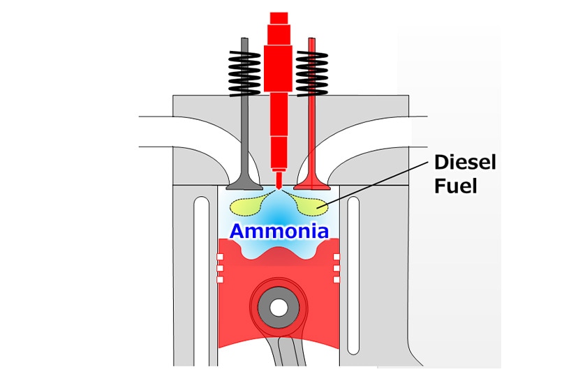
(Diesel fuel is used to overcome the poor ignitability of ammonia and achieve reliable ignition)
2. Development of Ammonia-Diesel Dual-Fuel Combustion
2-1. Three-Dimensional Numerical Simulation
The three-dimensional numerical simulation used in this study was developed using CONVERGE, a computational fluid dynamics (CFD) software package from the US company, Convergent Science. The inside of the engine’s combustion chamber was modeled in CONVERGE as an array of cells, as shown in Fig. 2. The software was then used to calculate the gas flow in each cell and the changes in temperature and pressure. A reaction mechanism was also incorporated to calculate the combustion reaction in each cell.
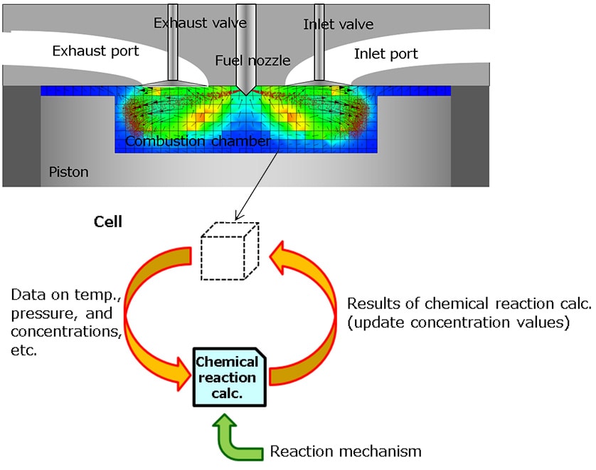
Fig. 3 shows the main reaction pathways that occur in ammonia combustion under typical conditions. It is known that, in the decomposition of ammonia (NH3) into N2 via intermediate products that include NH2 and NH, the combustion process also produces N2O and NO. By calculating the progress of these reactions in each cell, the simulation can estimate the distribution of each chemical species in the combustion chamber.
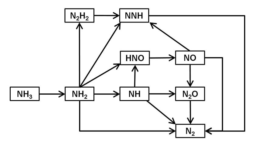
(Showing only Chemical Species Containing Nitrogen)
Typical Reaction Pathways 10-5 s after Reaction Commences at Pressure 6 MPa, Temperature 2000 K, and Equivalence Ratio of 0.5
2-2. Development of Reaction Mechanism
The chemical reactions that take place when fuels such as ammonia or hydrocarbons are combusted as a single fuel are well studied, with a variety of research institutions having published their own reaction mechanisms. Studies into the ignition characteristics of mixtures of ammonia and hydrocarbon fuel, on the other hand, are much rarer, and little has been published on the topic of dual-fuel reaction mechanisms. This makes it difficult to reproduce and predict the behavior of ammonia-diesel dual-fuel combustion using three-dimensional numerical simulation.
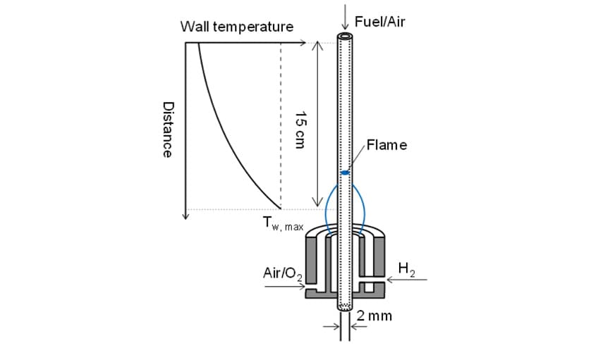
In response, this study partnered with the Energy Dynamics Laboratory at Tohoku University to develop a reaction mechanism for the dual-fuel combustion of ammonia and n-heptane. Here, n-heptane was used as diesel surrogate fuel. The ignition and reaction characteristics of ammonia and n-heptane were evaluated at Tohoku University using the combustion test apparatus shown in Fig. 4, a micro flow reactor with a controlled temperature profile. The micro flow reactor was a quartz glass tube with a diameter of about 2 mm and a wall temperature that was controlled by the flame from a burner. It allows for observation of the chemiluminescence that occurs when fuel and oxidizer are fed into the tube. Together with the temperature range, this chemiluminescence pattern can be used to determine the reaction characteristics of different fuels. Here, the results of testing in this micro flow reactor were used to assess the validity of the reaction mechanism for the dual-fuel combustion of ammonia and n-heptane.
3. Use of Three-Dimensional Numerical Simulation to Study Combustion in an NH3-Diesel Dual-Fuel Engine
The dual-fuel reaction mechanism developed through the joint research with Tohoku University was incorporated into the numerical simulation and used to reproduce ammonia-diesel combustion testing. The graph on the left in Fig. 5 shows good agreement between the results of numerical simulation and engine testing, both for the heat release rate and the gas pressure in the combustion chamber.
In terms of the concentrations of combustion products in the exhaust, the graph on the right in Fig. 5 shows how the exhaust concentrations of NO and NO2 increase as the mixing ratio of ammonia is increased. It also shows that very small amounts of N2O are emitted, except when the ammonia mixing ratio is zero. The numerical simulation successfully reproduced the quantitative results for the concentration of these combustion products in the exhaust.
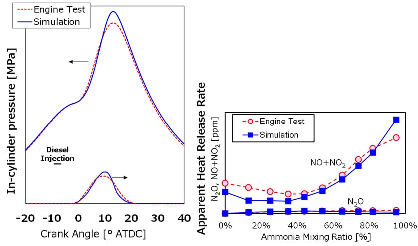
Reproduction of NO+NO2 and N2O Concentrations for Different NH3 Mixing Ratios (Right)
(Comparison of engine testing and simulation results)
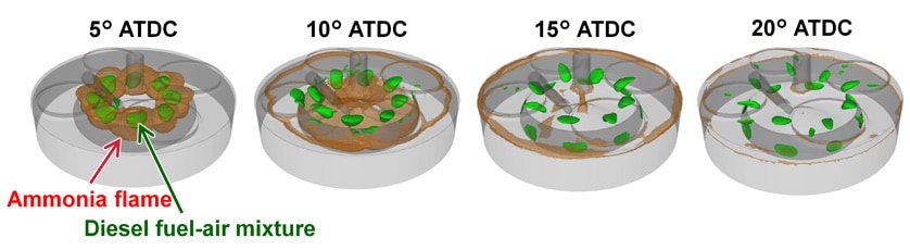
The numerical simulation results were presented visually to enable a detailed study of the combustion process and the distribution of combustion products. Fig. 6 shows the three-dimensional distribution of the diesel fuel-air mixture (green) and the ammonia flame front (brown) in the combustion chamber for 95% ammonia fuel. An ammonia flame front can be seen close to the diesel fuel-air mixture when the crank angle is 5° after top dead center (ATDC), after which the ammonia flame spreads throughout the combustion chamber. That is, the numerical simulation results provide a way to investigate how the ammonia flame spreads across the combustion chamber, with the injection of a very small amount of diesel serving as an ignition source.
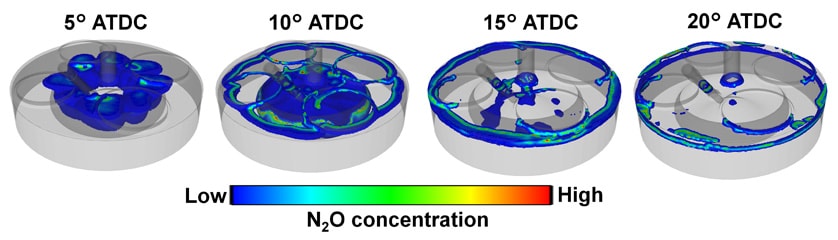
Next, the study looked at N2O, a well-known product of ammonia combustion, and investigated where in the combustion chamber it was being formed. While Fig. 7 shows how N2O is formed in the ammonia flame front, this N2O is in turn decomposed inside the flame. The high temperatures inside the flame cause N2O to decompose into N2 and other species. In the vicinity of the combustion chamber walls, however, such as the crevice between the piston and liner, residual N2O is still present when combustion has completed at 20° ATDC due to the effects of the wall temperature. This is likely to be the reason why ammonia engines emit N2O. In other words, this indicates that minimizing such crevices inside the combustion chamber should help to reduce N2O emissions.
In this way, the numerical simulation developed for this study can be used both to analyze the ammonia combustion process and to devise measures for improving efficiency or reducing combustion products.
4. Conclusions
This article has described the development of a three-dimensional numerical simulation for determining the basic combustion characteristics of ammonia and its use to analyze the ammonia combustion process and the distribution of the different combustion products. As a result, it was demonstrated that the use of ammonia fuel has the potential to reduce GHGs. In its ongoing efforts to reduce combustion products, Yanmar plans to conduct further research on emission reduction measures based not only on combustion, but also on the use of aftertreatment systems.
The authors also wish to acknowledge that the development of the numerical simulation described in this article drew on joint research with the Energy Dynamics Laboratory at Tohoku University, and to express their gratitude for this assistance.
References
- (1)Yuki Murakami, Hisashi Nakamura, Takuya Tezuka, Kenji Hiraoka, Kaoru Maruta, Effects of mixture composition on oxidation and reactivity of DME/NH3/air mixtures examined by a micro flow reactor with a controlled temperature profile, Combustion and Flame, Volume 238, 2022, 111911,
https://doi.org/10.1016/j.combustflame.2021.111911
-IMPORTANT-
The original technical report is written in Japanese.
This document was translated by Innovation & Technology Division, Technology Strategy Division.
Author
