 Agriculture
 Recreational Marine
 Recreational Boat
 Premium Cruiser
 Marine Equipment
 Marine Commercial
 Propulsion Engines (High Speed)
 Propulsion Engines (Medium Speed)
 Auxiliary Engines
 SCR System
 Dual Fuel Engine
 Two-stage Turbocharging System
 Electric Propulsion System
 Energy Systems
 Compact Equipment
 Industrial Engine
 Power Generation
 Compact Power Products
System Design Group
Development 1st Department
Development Division
Yanmar Energy System Co., Ltd.
YANMAR Technical Review
Development of Emergency Generators that Resolve Value Chain Issues
Remote Monitoring Services that Reassure Customers
Abstract
Maintaining the supply of electric power during disasters is an important part of business continuity planning, with one example being a 2022 earthquake in Japan that took out power to up to two million homes. With the number of such disasters rising, customers for emergency generators are experiencing a changing environment. Examples include anxiety about whether generators will function as needed when a disaster strikes and a desire to install systems on rooftops where they will not be at risk of flooding.
To create value for its customers and ensure that they can maintain a supply of power during disasters, Yanmar Energy System has developed the AP155F emergency generator that features a management system to ensure readiness when needed and a remote monitoring service.
1. Introduction
Emergency generators are a form of on-site backup generation that is used to supply power to firefighting or other emergency response infrastructure when electricity from the grid is unavailable for some reason, such as an earthquake. If used by more than a certain number of people, facilities such as commercial buildings are obliged by law (Fire Service Act, Building Standards Act) to install firefighting systems.
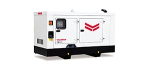
While emergency generators are driven by diesel engines or gas turbines, diesel generators account for more than 90% of all installations. This is because users appreciate the ease of storing diesel and the reliability of generator output. Yanmar Energy System Co., Ltd. (YES) is a leading supplier of emergency generators with models to suit different customer requirements ranging from small 5 kVA units up to large systems of 3,000 kVA or more.
This article describes the development of the AP155F emergency generator that addresses issues in the value chain and remote monitoring services that provide management infrastructure for ensuring disaster-readiness.
Table 1 AP155F Specifications
| No. | Parameter | Unit | AP155F | |
|---|---|---|---|---|
| 1 | Frequency | Hz | 50 | 60 |
| 2 | Rated output (standard model) | kVA | 138 | 152 |
| 3 | Rated output (long-duration model) | kVA | 138 | 152 |
| 4 | Engine | - | 6F104T2-GL | |
| 5 | Speed governor | - | Common rail | |
| 6 | Rated output of engine | kW | 170 | 210 |
| 7 | Fuel | - | Diesel, LSA fuel oil (cetane number ≥ 45) | |
| 8 | Fuel consumption (long-duration, package model) | L/h | 29.4 | 33.9 |
| 9 | Cooling | - | Radiator (electric fan) | |
| 10 | Battery voltage and capacity | V-Ah | 12-80 | |
| 11 | Radiator air flow | m3/min | 140 | 165 |
| 12 | 75-dB package dimensions (LxWxH) | m | 3.9x1.1x2.3 | |
| Installation footprint | m2 | 4.29 | ||
| Installed weight | kg | 2520 | ||
2. Development Background
YES strives to enhance its products to overcome issues faced by customers. Fig. 1 shows two key issues identified from an analysis of the value chain.
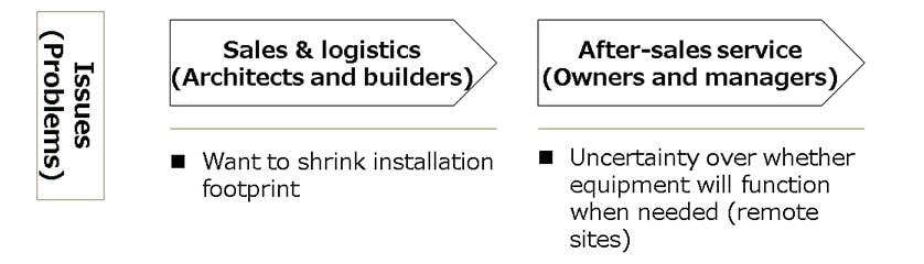
2-1. Uncertainty over whether Equipment will Function when Needed (Issue for Facility Owners and Managers)
If their maintenance is neglected, there is a risk that emergency generators may run out of fuel or have reliability issues when they are needed. A survey found that, during major earthquakes in the past, 4.8% of emergency on-site power supplies in regions where the seismic intensity was six or higher either failed to start or halted due to problems such as battery degradation or a lack of fuel. The emergency generator industry has found it difficult to keep track of equipment condition due to the need to send out skilled technicians to assess this on-site. To address these customer concerns about whether their equipment will function when needed, YES has developed a status monitoring service and a remote monitoring service that includes assessment of equipment degradation.
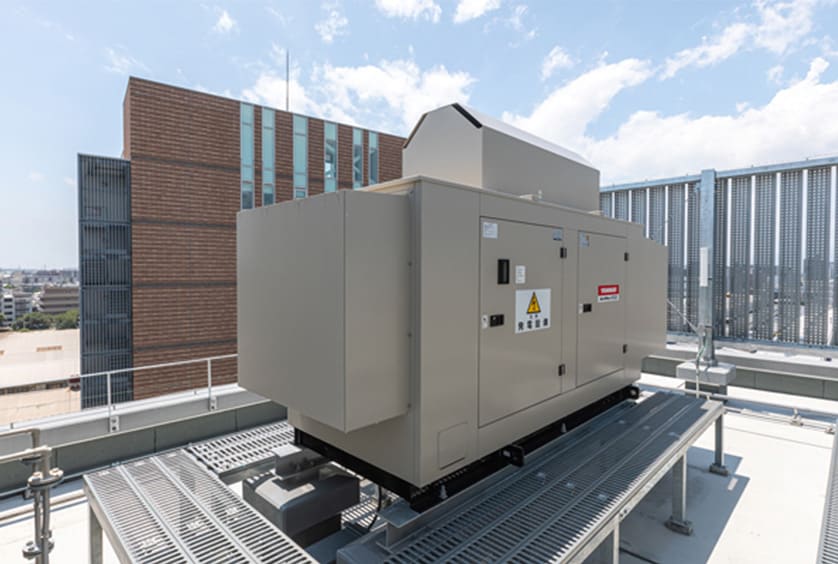
2-2. Desire to Shrink Installation Footprint (Issue for Facility Owners and, Architects, and Builders)
During Typhoon Hagibis (Typhoon No. 19), which struck the Kanto region of Japan in 2019, the flooding of high-voltage electrical distribution equipment in the basement of a high-rise condominium put the elevators, water supply, and other essential services out of action for a time. In response, the Ministry of Land, Infrastructure, Transport and Tourism and the Ministry of Economy, Trade and Industry jointly developed the “Guidelines for Measures against Flood Disasters at Electricity Facilities in Buildings” for circulation to regional public agencies and relevant industry organizations. The guidelines recommended that electrical equipment be installed at locations with a low risk of flooding and advised that, in the future, effective use be made of the limited space available for installing such equipment. For customers facing the difficulty of how to reduce the footprint of generation equipment, an effort was made with the AP155F to extend YES’s industry leadership in terms of shrinking the package size.
3. Measures for Emergency Readiness
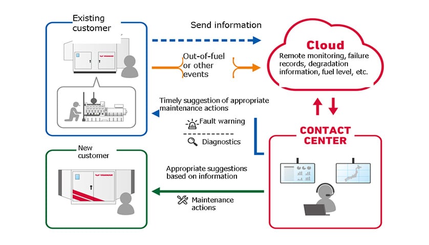
YES led the industry with the launch in 1984 of its Remote Energy Support System (RESS). To address customer concerns about whether their equipment will be available when needed, YES now offers two remote monitoring services especially designed for emergency generators. These feature the centralized management at the YES contact center of information collected by a new remote communications unit installed in the AP155F, including fuel level and the extent of battery degradation. Fig. 3 shows a block diagram. Through the services described below, it is expected that, out of sites where equipment failed to operate during past major earthquakes, approximately 61% would have functioned had the services been used.
3-1. Status Monitoring Service
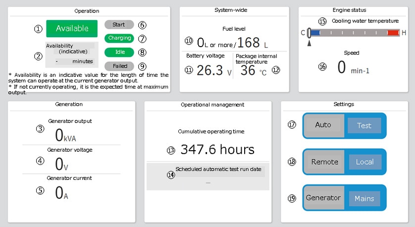
The status monitoring service provides a visual overview of generator status from a single screen on a personal computer, smartphone, or tablet. This gives customers an easy way to verify the condition of their generators and their readiness to operate ([1] in Fig. 4), even at remote sites. Another issue is when settings are changed on the generator control panel ([17] and [18] in the Fig. 4) such as when testing operation during a routine inspection. If the inspector forgets to restore the previous settings afterwards, the generator may not start when needed. With this service, however, the site owner or manager can check settings at any time to ensure generator readiness.
3-2. Remote Monitoring Service
The remote monitoring service has been augmented with functions for assessing the condition of parts that require maintenance (such as batteries) and for reporting the available operating time.
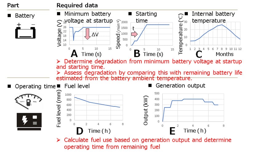
The first of these functions assesses the extent of battery degradation and calculates the estimated life remaining using operation data from startup and the ambient temperature by the battery. In practice, this involves measuring the minimum battery voltage at startup (see Fig. 5-A) and starting time (Fig. 5-B) to record the startup voltage drop (ΔV) and starting time (t), two parameters that tend to increase toward the end of the battery life. By utilizing these characteristics, the extent of battery degradation can be determined by comparing the result with the remaining battery life estimated from the battery ambient temperature (Fig. 5-C). This avoids downtime at the site during a disaster by enabling pre-emptive action to prevent a battery problem from causing the generator to not start when needed.
The second function is implemented at the contact center (Fig. 3) and calculates the total remaining fuel in units of liters based on the fuel levels in the AP155F fuel tank and any external fuel tanks (the fuel level in customer tanks can also be collected) (see Fig. 5-D). The system at the contact center also has a fuel-use map (for each generator output level and fuel type) and automatically determines the rate of fuel use based on actual output (see Fig. 5-E) when the generator is running or the use assuming rated output when idle. Finally, the function displays and reports the remaining operating time (hours) which it calculates by dividing the remaining fuel (L) by the rate of use (L/hour). This function is provided to help customers who want to know how much operating time is available at remote sites where it is not possible to check the fuel level in person.
4. Measures for Reducing Installation Footprint
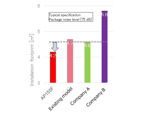
The emergency generator’s engine fan is used to cool the engine room and radiator. While this fan is normally located near the outlet hood, this hood was made larger due to the loudness of the equipment when operating. Also, as the cooling path for the radiator also goes through the engine room, it was designed to allow a large amount of air flow. A problem with this was that, because negative pressure is maintained inside the package to prevent rain from getting into the intake hood, the hood ended up being larger than necessary. To meet the anticipated rise in market demand for smaller package sizes, the fan drive mechanism (outlet hood) and airflow (intake hood) on the new generator were redesigned (see Fig. 6) to achieve a best-in-class installation footprint of only 4.2 m2 (see Fig. 7).
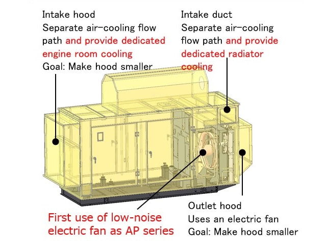
4-1. Redesign of Fan Drive Mechanism (Adoption of Low-noise Electric Fan)
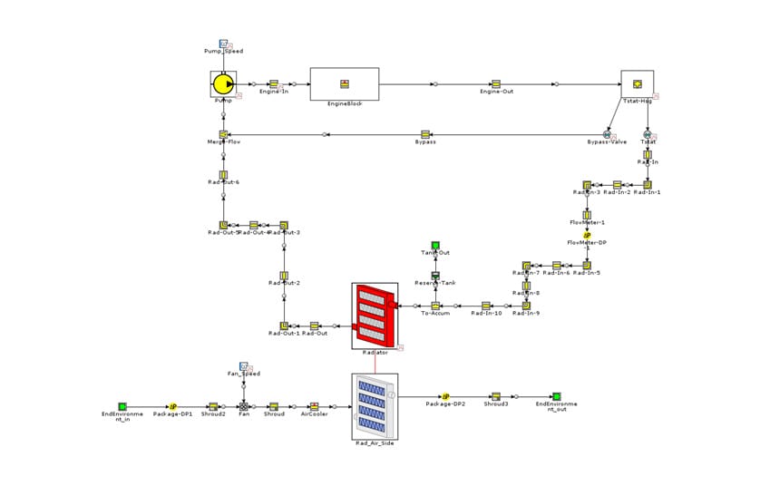
In a new innovation, the cooling fan was separated from the engine to reduce noise as described above and an electric motor was used to drive the fan. As engine fans are belt-driven by the engine, they frequently operate at high speeds (2,000 min-1 or higher) and tend to be noisy. Replacing the engine fan with a low-noise electric fan allows for quieter operation because it can run at a slower speed (such as 1,500 min-1 or 1,800 min-1). To select the electric fan, a cooling water circuit model was first developed based on the intended radiator specifications and used to determine the fan air flow required for cooling and the radiator core size needed to achieve a cooling water temperature of less than 100°C at the engine outlet (see Fig. 9). The required P-Q characteristic of the fan (an indicator of fan performance expressed in terms of the air flow vs. static pressure) was determined from this air flow requirement, the air resistance of the radiator, and the resistance to airflow through the package and in the ducting used for indoor installations, taking account of the airflow design discussed in more detail below. Selecting a low-noise electric fan that satisfied these P-Q characteristics reduced the noise level by 26% compared to use of an engine fan. As a result, the outlet hood was made 60% smaller than on the previous model (see [1] in Fig. 8).
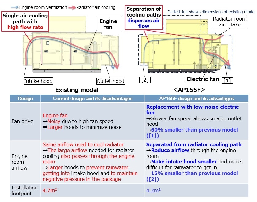
4-2. Redesign of Engine Room Airflow (Separation of Cooling Paths)
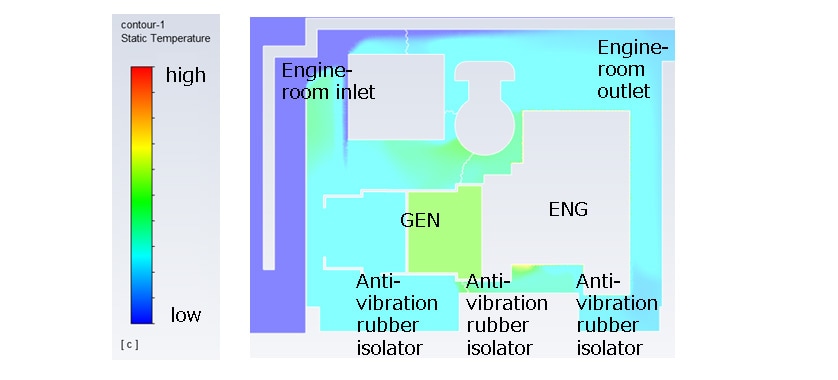
To make the intake hood smaller, the engine room and radiator cooling were separated from one another for the first time in the AP series. The distribution of heat in the engine room was simulated to determine the minimum quantity of air through the intake hood needed for engine room ventilation (indicated by the blue arrow in [2] in Fig. 8). As the anti-vibration rubber engine isolators influence part life, these were used as a benchmark to determine how much air flow was needed to keep the temperature at the outlet of the engine room at the target temperature or below. This analysis found that the air flow through the intake hood could be reduced by 47% compared to the existing model. This reduction in air intake also facilitates improvements in rainwater infiltration and negative pressure in the package and it allowed the intake hood to be made 15% smaller than the existing model.
5. Conclusions
In the AP155F emergency generator described in this article, YES has developed a product that can help resolve issues in the value chain through a reduction in installation footprint and the provision of remote monitoring services for customers concerned whether their equipment will function when needed.
As a leading supplier of emergency generators, YES intends to continue providing customers with ways of implementing business continuity planning (BCP) in the form of energy solutions that help resolve the challenges they face.
6. References
- (1)Guidelines for Measures against Flood Disasters at Electricity Facilities in Buildings
https://www.meti.go.jp/press/2020/06/20200619003/20200619003.html
-IMPORTANT-
The original technical report is written in Japanese.
This document was translated by Innovation & Technology Division, Technology Strategy Division.
Author
