Research & Development Center
Innovation & Technology Division
YANMAR HOLDINGS CO., LTD.
YANMAR Technical Review
Energy Conversion from Waste Heat to CO2-Free Electric Power: Development of kW-Class Thermoelectric Power Generator with Loop Thermosiphon Heat Exchanger
Abstract
In order to enable the reduction of CO2 emission, Yanmar has been studying the power generation that uses exhaust heat generated from various industries. Thermoelectric power generation is suitable for the practical exhaust heat power generation because of compact size, no moving parts and workability. To generate kW-class electric power, it is necessary to use a heat exchanger with high heat transport capacity. In this article, as a technology of exhaust gas heat recovery, a thermoelectric power generator using a loop thermosiphon heat exchanger to recover the heat from exhaust gas with high durability has been developed.
1.Introduction
Achieving carbon neutrality requires the early practical deployment of technologies for saving energy and reducing CO2 emissions. In the energy conversion sector, the utilization of thermal energy that would otherwise go to waste is recognized as one of the many different energy-saving measures available(1). Focusing on industrial waste heat as a prime example of such thermal energy, the heavy commercial energy users covered by the provisions of Japan’s Energy Conservation Law require kW-class energy savings. Unfortunately, little progress has yet been made because it can be difficult to supply solutions that satisfy the varying requirements of energy efficiency (using waste heat to reduce fuel or electricity consumption), compatibility with available sources of waste heat, and economics (return on the cost of installation).
Thermoelectric power generation utilizing waste heat by converting it into CO2-free electric power is a good way to meet both the compatibility and economic requirements because it is easy to install on waste heat ducts, with a simple design that is compact and has no moving parts. The characteristics of thermoelectric power generation also allow it to deliver energy savings, being able to generate electric power in the kW range when combined with a high-thermal-transport-capacity heat exchanger. Accordingly, Yanmar has developed a kW-class thermoelectric power generation system that is equipped with a loop thermosiphon heat exchanger. This article describes this newly developed technology with reference to the performance required for the practical deployment of thermoelectric power generation systems in society.
2.Performance Requirements for Practical Deployment of Thermoelectric Power Generation System
To be viable in terms of energy efficiency, the system requires a means of recovering usable heat and converting it into electric power in the kW range despite the low exergy*1 of the waste heat source. Similarly, the compatibility requirement calls for a system design that is compact and easy to install, such that it is able to fit into the confined space available around ducts or other waste heat sources. Finally, to be economically viable, the system must have an operating life of 10 years or more and deliver substantial economic benefits relative to using commercial electricity. The following sections describe how these requirements for energy efficiency, compatibility, and economics are fulfilled while also explaining the principle of thermoelectric power generation.
- *1Exergy is the theoretical maximum amount of work a system can perform from a given amount of energy when brought into thermodynamic equilibrium with its environment.
3.Technology that Combines Energy Efficiency, Compatibility, and Economics
3.1.Principle of Thermoelectric Power Generation
Thermoelectric power generation utilizes the Seebeck effect*2 to generate an electromotive force from the temperature difference across a thermoelectric semiconductor material or bimetallic junction (thermoelectric element) sandwiched between two substrates, as shown in Fig. 1(2). The combined thermoelectric elements, substrates, and electrodes are called a thermoelectric module. As the electrical output of a thermoelectric module is proportional to the square of the temperature difference, how to transport the waste heat to the module is a key design consideration.
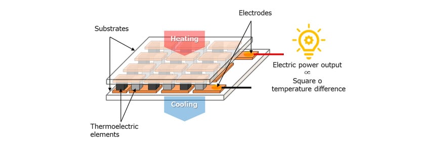
- *2When two dissimilar metals or semiconductors are bonded, an electric potential is generated between two contacts if they are kept at different temperatures. This is called a thermoelectromotive force and the associated phenomenon that generates this force is called the Seebeck effect.
3.2.kW-Class Thermoelectric Power Generation System Using Loop Thermosiphon Heat Exchanger
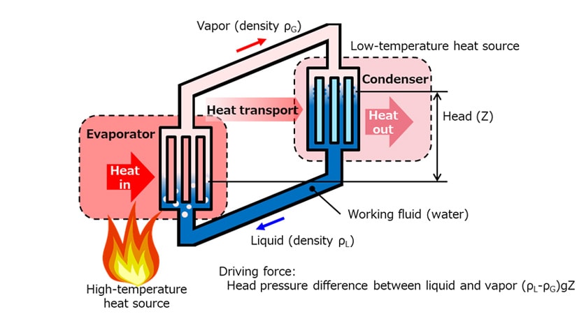
One of the challenges of generating electric power from waste heat is that its comparatively low exergy limits the amount of power generated. Accordingly, a heat exchanger with high heat transport capacity is needed to convey the waste heat to the thermoelectric module. For this reason, Yanmar chose to use a loop thermosiphon heat exchanger that works by latent heat exchange because of the superior heat transport capacity of this type compared to sensible heat exchangers. As shown in Fig. 2, a loop thermosiphon heat exchanger functions by evaporating and condensing the working fluid in a closed loop and can transport heat without the need for an external power source. Furthermore, by having a gradient (height difference) between the evaporator and condenser, the difference in head pressure between the liquid and vapor is additionally utilized to drive circulation.
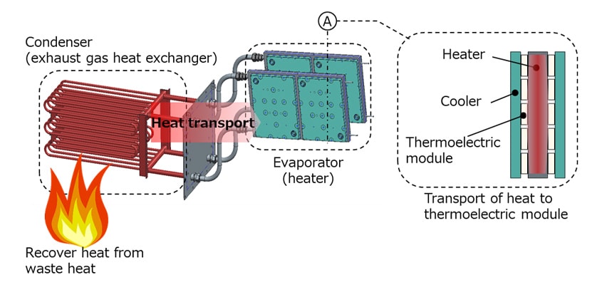
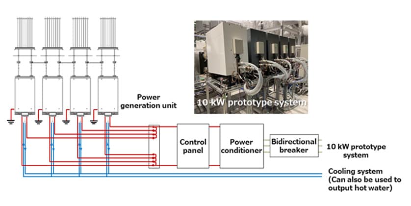
Fig. 3 shows a diagram of the thermoelectric power generation unit. The exhaust gas heat exchanger and the heater correspond to the evaporator and condenser, respectively, in Fig. 2. The exhaust gas heat exchanger is inserted in an exhaust duct and uses evaporation of coolant to recover heat. The evaporated coolant (steam) travels from the exhaust gas heat exchanger to the inside of heater where it condenses, releasing the latent heat of condensation to the thermoelectric module. The system design has a number of thermoelectric modules attached to both sides of the heater, sandwiched with the coolers on their outer sides. Cooling water flows through these coolers to maintain the temperature of the cold side of each thermoelectric module. While each of the thermoelectric power generation units shown in Fig. 3 can generate around 2 kW of electric power, a total power generation can be increased by installing a number of these units in tandem, as shown in Fig. 4. The direct current output is converted to alternating current in a conventional power conditioner and supplied to the electricity distribution system, thereby reducing both the consumption of commercial electricity and CO2 emissions. A 10kW-class power generation system made up of multiple thermoelectric units and operating for 7,200 hours/year, for example, would deliver a 33-ton annual reduction in CO2 emissions based on a CO2 emission intensity(3) of 0.000453 ton-CO2/kW. At sites where the demand exists, the heat recovered by the thermoelectric power generation unit can also be delivered in the form of hot water.
3.3.Thermoelectric Power Generation System Featuring Easy Installation
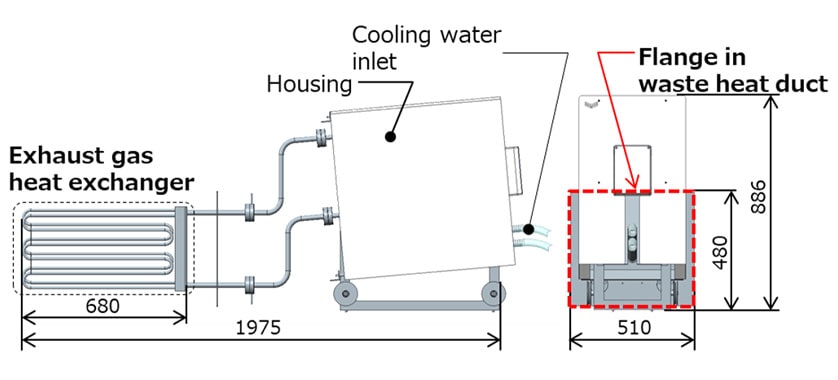
Fig. 5 shows a schematic diagram of a thermoelectric power generation unit. The heater, thermoelectric module, and cooler are all packaged inside the housing and all that is needed to operate the unit is a supply of cooling water. Similarly, the exhaust gas heat exchanger can be inserted in an exhaust duct simply by bolting the flange to the duct shown in Fig. 5.
3.4.Extended Operating Lifetime Using a Sandwich Heat Transfer Configuration
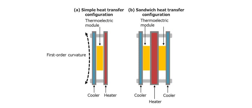
Because this unit has a heater that transports heat to the thermoelectric module on one side and a cooler that removes surplus heat on the other, as shown in Fig. 6 (a), simply connecting these three components together would result in physical deformation (first-order curvature) due to the thermal expansion of the hot side. The thermoelectric power generation unit developed here was designed to minimize this curvature and ensure a longer operating lifetime by adopting a sandwich heat transfer configuration. This configuration prevents excessive stresses in the thermoelectric modules by positioning the heater in the center with thermoelectric modules on either side and coolers on the outer sides of the thermoelectric modules. Durability testing involving the cyclic application of thermal expansion indicated an operating lifetime of 10 years or more, verifying that the economic benefits of the system compare well with the use of commercial electricity.
4.Conclusions
Through the use of a loop thermosiphon heat exchanger and a sandwich heat transfer configuration, Yanmar succeeded in developing a thermoelectric power generation system with excellent energy efficiency, compatibility, and economic performance. The developed system features 2-kW-class thermoelectric power generation units that can also be connected in tandem to increase power output. The design is also easy to install and has an operating lifetime of more than 10 years. Installing a 10-kW-class thermoelectric power generation system can reduce annual CO2 emissions by about 33 ton. Through the practical deployment of thermoelectric power generation systems, Yanmar is contributing both to improving energy efficiency in industry and to reducing CO2 emissions as it works toward achieving carbon neutrality by 2050.
Acknowledgements
Some of the work described in this article was undertaken as part of a project commissioned by the Ministry of the Environment for the “Development and Testing of Enabling Technologies for Strengthening Measures for Reducing CO2 Emissions” (4). The authors would like to express a deep gratitude for its support.
References
- (1)New Energy and Industrial Technology Development Organization (NEDO), Toward Future Use of Unutilized Thermal Energy, Document for INCHEM TOKYO 2019 special lecture in Japanese.
- (2)R. Funahashi, et al., Thermoelectrics Society of Japan, Fundamentals and Applications of Thermoelectrics – Guidepost to Green Society, CMC Publishing, 2018 in Japanese.
- (3)Ministry of the Environment, System for Calculation, Reporting, and Publication of Greenhouse Gas Emissions, Webpage for Utility-Specific Emission Intensity, Utility-Specific Emission Intensity, Actual Data for FY2020, Values for each Transmission and Distribution Utility, in Japanese.
(https://ghg-santeikohyo.env.go.jp/calc/denki) - (4)Contract for Ministry of the Environment, FY2020 Development and Testing of Enabling Technologies for Strengthening Measures for Reducing CO2 Emissions, Commissioned Project for Development and Testing of Compact Thermoelectric Power Generator with High Output Using Thermosiphon Heat Exchanger – Results Report, in Japanese.
-IMPORTANT-
The original technical report is written in Japanese.
This document was translated by Innovation & Technology Division, Technology Strategy Division.
Author
