Technology Development Department
Development Department
KANZAKI KOKYUKOKI MFG.CO., LTD.
YANMAR Technical Review
Motor Thermal Analysis for Electrification of Machinery
Thermal Analysis of Electric Motors Using Finite Element Method and Thermal Equivalent Circuit
Abstract
Recently, the demand for environmental performance has been increasing in the automobile industries and other industries. Therefore, our company is also developing an electric transmission. In the development of electric products such as motors, the problem of heat is very important, because the temperature rise of parts may cause decrease of performance and safety, and decrease efficiency. It is important to make predictions in advance using analysis technology so that such situations do not occur. Therefore, thermal analysis was performed using a method that combines finite element analysis and thermal equivalent circuit analysis, and a tendency was obtained that the test results and the analysis results were in good agreement. We will apply the constructed method to motors under development and contribute to timely product development.
1. Introduction
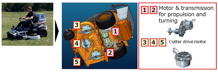
Like the automotive sector, the machinery industry has seen rising demand for environmental performance (reduced carbon emissions) over recent years and this has led to increased effort going into electrification as a means of achieving zero emissions. The electrification of machines driven by internal combustion engines (ICEs) also brings added value in the form of quieter, maintenance-free operation. Kanzaki has also been pursuing electrification as a means of satisfying these requirements, including work on electric transmissions for ride-on lawn mowers (see Fig. 1). This article discusses the challenges posed by electrification and describes work on the thermal analysis of electric motors, a key component in electric drive systems.
2. Challenges of Electrification
2-1. Challenges Posed by Electrification of Machinery
Short operating time is a well-known issue with electric machines compared to their ICE equivalents, a consequence of the low energy density of batteries. Another problem is the reduction in output caused by heat generated by the transmission, motor, and other electric drive train components. This makes the thermal design process for achieving heat balance especially important.
Because performance requirements, operating conditions (external environment), and space constraints tend to vary by application in the case of machinery, it is difficult to engineer a single uniform system for their electrification as is possible with automobiles. Instead, each machine requires its own system and thermal design. Table 1 lists example requirements for the electrification of different types of machinery. In addition to those listed in Table 1, each machine also has its own requirements for output and installation space. When electrifying an existing ICE-powered machine, such as an agricultural or construction machine powered by a water-cooled diesel engine, it is possible to use the same cooling system for the electric motor. In this case, however, Kanzaki is seeking to electrify a lawnmower powered by an air-cooled gasoline engine in which space and cost constraints restrict the ability to install additional components such as a fan or water cooling pump. Likewise, the low speed of a lawnmower compared to a car (around 10.8 km/h) does not provide enough air flow for natural air cooling to be a viable option for electric motor cooling. Given that these installation and cooling criteria are different for each machine, optimal thermal designs that allow for these factors play a crucial role in the electrification of such machinery.
Table 1 Example Requirements for Electrification of Machinery
| Propulsion | Non-propulsion (hydraulic pump drive, cutting blades) |
Ease of cooling | ||||
|---|---|---|---|---|---|---|
| Natural air cooling | Forced air cooling | Water cooling | Oil cooling | |||
| Lawnmowers | Low-speed | Rotate blades at constant speed | ○ | × | × | × |
| Agricultural machinery | Low-speed to high-speed | Operate hydraulic pump at high efficiency | ○ | △ | ○ | △ |
| Construction machinery | Low-speed | ○ | △ | ○ | △ | |
(○: Easy, △: Possible by adjusting installation conditions to suit, ×: Difficult)
2-2. Challenges in Electrification of Transmissions
As transmissions typically involve the rolling and slipping motions of meshing gears and bearing contact surfaces, they are subject to friction losses. These losses are converted into thermal energy that diffuses into the transmission equipment and raises its temperature.
As an electric transmission, on the other hand, is connected to an electric motor and inverter in place of the engine, the electrical losses from these components are added to the mechanical losses and likewise contribute to the temperature increase. When the temperature of surrounding components rises, it makes it more difficult for heat to dissipate from coils, electronic components, and other heat-sensitive parts in the motor and inverter, causing those parts to get even hotter and degrading their efficiency, performance, and safety. The use of small and lightweight components is vital when seeking to replace an engine with an electric motor. The drive system and batteries need to fit in the limited space available while still achieving an output similar to the engine-powered machine. However, smaller size means more concentrated heat and makes the system even more prone to temperature rise. This in turn makes it important when developing a small and lightweight electric transmission to have thermal analysis methods available that can estimate temperature rise at the design stage. Unfortunately, the simplified methods in current use are problematic, delivering temperature predictions that differ significantly from experimental results. As a first step toward putting the relevant technologies in place, Kanzaki has been working on a thermal analysis technique specifically for electric motors that is easy to use in the early design stages and achieves an accuracy of within ±5°C.
3. Thermal Analysis
3-1. Types of Heat Transfer and Analysis Techniques
To perform thermal design, it is necessary to know what forms of heat transfer are taking place. Here, heat transfer refers to the flow of thermal energy from a higher to a lower temperature location. This can take the form of conduction, heat exchange, and radiation, each of which works by a different mechanism. Table 2 lists their respective characteristics.
Table 2 Types of Heat Transfer(1)
| Heat transfer | Mechanism |
|---|---|
| Conduction | The transfer of heat within a material. This mainly refers to the transfer of heat due to thermal gradients in solid bodies. |
| Heat exchange (convection) | Heat transfer by the exchange of heat. This mainly refers to the transfer of heat between solid bodies and liquids. |
| Radiation | The radiation of heat from the surface of a body as electromagnetic energy
|
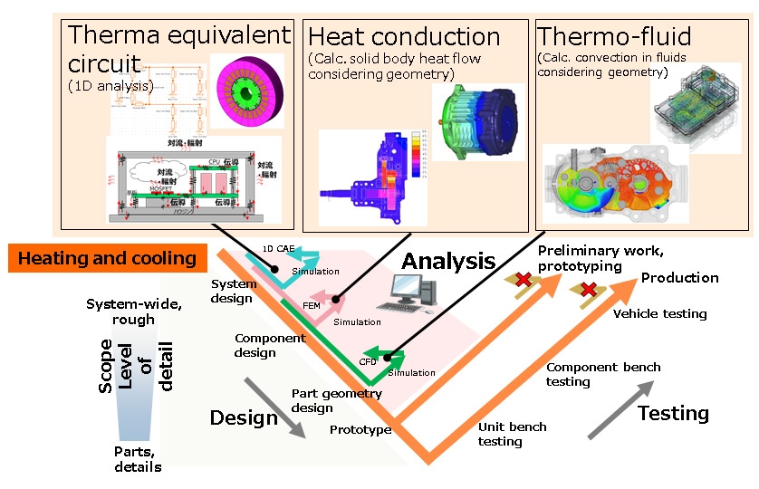
Three ways in which the heat transfers listed in Table 2 can be calculated are thermal equivalent circuit analysis, heat conduction analysis, and thermo-fluid analysis. Table 3 lists these methods in terms of their accuracies and computation times. Given the tradeoff between accuracy and computation time, the ability to use thermal equivalent circuit analysis for the quick evaluation of different design options means it is used in the early design stages to determine what cooling methods and areas will be needed to achieve heat balance, as shown in Fig. 2. More accurate analyses are typically performed as the design progresses, using heat conduction analysis based on part geometry and thermo-fluid analysis to also consider the associated fluids. In this way, the design is progressively refined by choosing the analysis method that best suits each stage of the design process, enabling work to be front-loaded to minimize the amount of trial and error.
Table 3 Characteristics of Different Thermal Analysis Methods(2)
| Analysis method | Characteristics | Accuracy | Computation time |
|---|---|---|---|
| Thermal equivalent circuit (1D analysis) |
|
Low | Quick |
| Heat conduction (Finite element) |
|
Medium | Moderate |
| Thermo-fluid |
|
High | Long |
4. Example Analysis
4-1. Combination of Thermal Equivalent Circuit and Finite Element Method
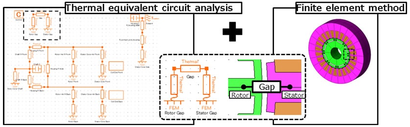
In this case, the thermal analysis was performed using a function supplied as part of the electromagnetic field analysis software (the JMAG package supplied by JSOL Corporation(3)) that combines a thermal equivalent circuit with the finite element method. As this method provides good accuracy with reasonable calculation time, it was used for the early design stages. As shown in Fig. 3, the more accurate finite element method was used for key motor components (coil, stator, and rotor) while the remainder of the thermal circuit was modeled as a thermal equivalent circuit. This allowed for many different design options to be analyzed quickly and accurately.
4-2. Matching of Combined Thermal Equivalent Circuit and Finite Element Method to Actual Heat Flows
he analysis technique was applied to the naturally cooled bench testing apparatus shown in Fig. 4 for a motor intended for a ride-on lawn mower.
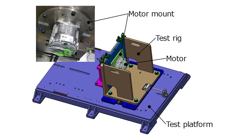
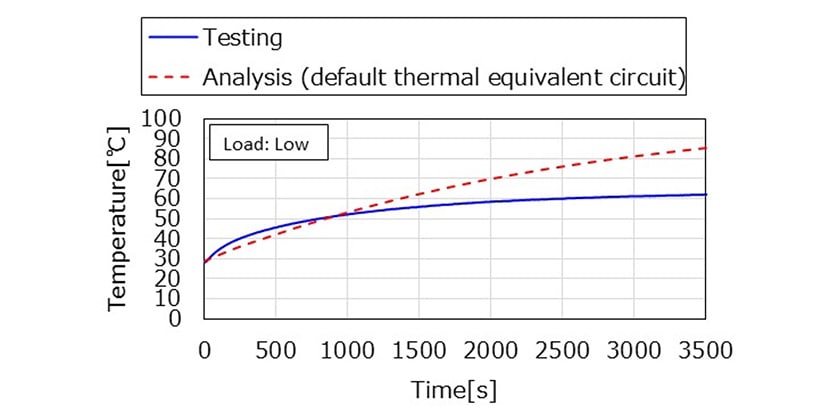
Fig. 5 shows a comparison of the coil temperatures under low load conditions obtained by experimental testing and from an analysis performed using the default thermal equivalent circuit provided in JMAG. The analysis shows a continuously rising temperature, a different result to that obtained by testing. That is, the result indicated that heat generation and dissipation were not in equilibrium and that some heat transfer was missing from the analysis. It was concluded that the analysis was not adequately considering the pathway whereby heat generated in the motor flowed to the motor mount and from there to the atmosphere.
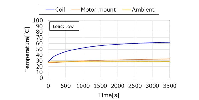
To test this hypothesis, the temperature of the motor mount was measured (see Fig. 6). As the temperature of the motor mount rose in tandem with the coil temperature, this indicated that heat generated in the motor was flowing to the mount.
As these results indicated that the heat transfer path to the motor mount could not be ignored, the thermal equivalent circuit was updated (as shown in red in Fig. 7) to reflect the actual heat flow pathway and the new configuration was tested.
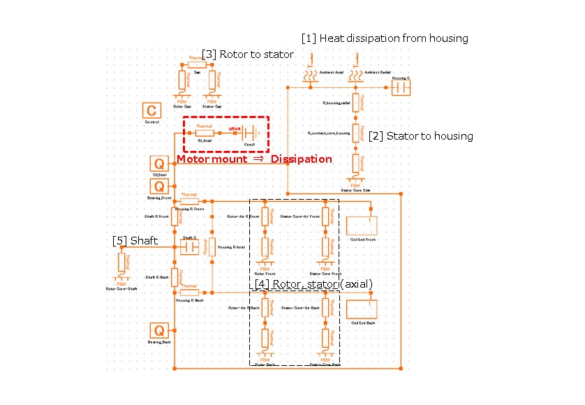
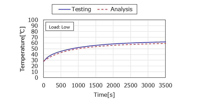
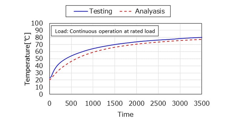
Fig. 8 and Fig. 9 show comparisons of the coil temperatures obtained using this circuit when operating at low load or continuously at rated load. By using a circuit that is better matched to the actual heat flow, good agreement between experiment and calculation was obtained under both conditions. While the error is larger for higher loads (2.2°C for rated load vs. about 0.4°C for steady state operation at low load), this is within the target accuracy of ±5°C and is considered adequate for use as a tool in the early design stages.
4-3. Electrification of Machinery
The study confirmed that this method can achieve accuracy of within ±5°C for a naturally cooled motor. While the method only covers a limited range of conditions, it enables the motor temperature to be predicted and is easy to use in the early design stages. As such, it represents a successful first step toward putting the technology for thermal analysis in place.
Three challenges remain to be addressed. The first is to eliminate the divergence between the calculated and measured temperatures during the period immediately after starting the motor. This is needed to enable analysis of the motor operating at rated conditions for short periods. The second challenge is to investigate thermal analysis techniques that can handle the water, oil, or other cooling systems that will be needed when using motors with higher outputs. The higher losses that come with more powerful motors make heat balance more difficult to achieve. The third challenge will be to investigate techniques for system-wide thermal analysis that also encompass the electric transmission and vehicle body rather than just the motor on its own. Overcoming these challenges will enable optimal thermal design by providing highly accurate machine-specific temperature predictions.
5. Conclusions
Recognizing that thermal analysis is a key factor in the development of small and lightweight electric transmissions, this article has described a study of how to achieve temperature prediction accuracies of within ±5°C in the early design stages. In the future, Kanzaki intends to establish thermal analysis methods that encompass entire systems and to add support for water, oil, or other forms of cooling so that optimal cooling systems can be devised at the same time as determining machine or vehicle specifications. By developing this technology, Kanzaki intends to deliver high-quality solutions through the electrification not only of ride-on lawn mowers, but also a variety of other machinery.
References
- (1)Masayuki Morimoto, Thermal Countermeasures for Electric Motors: Analysis & Evaluation, Heat-Resistant Materials, and Heat Dissipation and Cooling Design, NTS Co. Ltd., 2022
- (2)JSOL Seminar Document, Seminar on Thermal Analysis for Motor Design, 07/13/2022
- (3)JSOL, JMAG: Simulation Technology for Electromechanical Design
https://www.jmag-international.com/jp/ - (4)ISO/TR 14179 Gears-Thermal capacity-
-IMPORTANT-
The original technical report is written in Japanese.
This document was translated by Innovation & Technology Division, Technology Strategy Division.
Author