Research & Development Center
Research & Development Unit
YANMAR Technical Review
Novel Thermal Management in an Engine Room using Non-Parametric Sensitivity Analysis
Abstract
Thermal management of industrial vehicles is made difficult by the fact that they are operated under a heavy load and at low traveling speed. They also tend to be operated for long periods of time within the same area, making them a greater cause of high noise levels than passenger cars. Although running the cooling fan at a faster speed or making the engine room larger can enhance cooling, these measures also result in more noise. Therefore, industrial vehicle design requires ways of achieving both thermal management and low noise. In this study, non-parametric sensitivity analysis is applied to the engine room of an agricultural tractor in order to determine the sensitivity of design variables to coolant temperature. Using non-parametric sensitivity analysis results in a lower computational load than conventional parametric approaches to engine room design.
1. Introduction
Industrial vehicles are characterized by operating at a higher engine load and generating more heat than passenger cars. And also they travel more slowly and their ram pressure is low compared to the total pressure from the cooling fan. These conditions make thermal management of their engine rooms difficult. Furthermore, because industrial vehicles operate for long periods of time within the same area, they also tend to be responsible for high levels of ambient noise. While the problems with heat can be dealt with by running the cooling fan at a faster speed or making openings of the engine room bonnet larger, both of these exacerbate the noise level. Although the noise level has been reduced to comply with the certification of the Ministry of Land, Infrastructure, Transport and Tourism and European Union (EU) certification systems for acoustic power levels, and to ensure user comfort; there remains a need for engine room design techniques for industrial vehicles that can deal with both thermal management and noise reduction.
One technique adopted at the design stage is to use computational fluid dynamics analysis to examine the heat convection field. However, further optimization of designs that have devolved over time is not easy. Available methods include the use of parameter studies to obtain regression formulas or response surfaces. and determine the sensitivity of an objective function to design variables, and the use of optimization algorithms such as the gradient method or global search techniques to obtain the optimal solution(1). Although these parametric techniques can produce the design guidelines, they require the selection of appropriate design variables and large numbers of experimental or computational results. Another approach is to use non-parametric sensitivity analysis. This involves formulating the heat convection field design problem based on the variational method and using numerical methods to solve the resulting adjoint problem. Examples include research on shape optimization for aircraft in compressible convective fields(2), and research on layout optimization for building ventilation in incompressible heat convection fields(4). These methods involve obtaining the design variable sensitivities at the boundary surfaces using a direct analysis to obtain an initial solution, and inverse analysis to obtain the sensitivities, which are defined as variations in the objective functional with respect to small variations in boundary conditions.
In this study, non-parametric sensitivity analysis is applied to heat problems in the engine room of an industrial vehicle in order to determine the design sensitivity of the controllable factor of the engine coolant temperature such as the bonnet open area ratio. This analysis results in a lower computational load than conventional parametric approaches.
2. Definition of problem
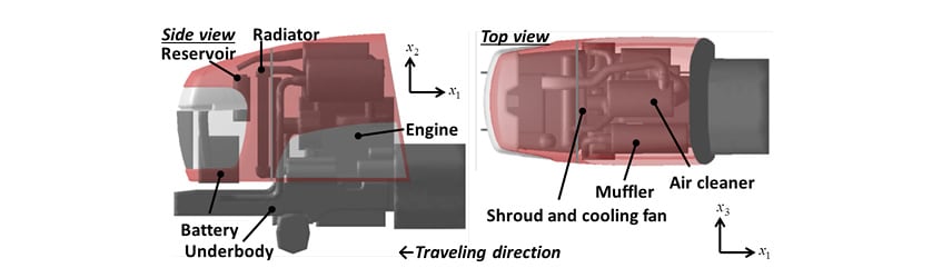
Fig. 1 shows an agricultural tractor installed with a water-cooled diesel engine with rated output of 21 kW for the study.
The designers evaluate the radiator inlet temperature, for the purpose of preventing engine overheating. Therefore, an equation needs to be formulated forAssuming thermal equilibrium, the following equation expresses the heat
 that flows from the engine’s combustion chambers to the water jacket.

Here, and
and are the coolant heat as a proportion of the lower calorific value of the consumed fuel, engine output, specific fuel consumption, and the lower calorific value of diesel fuel respectively. The radiator inlet coolant temperature,and outlet temperature,
 are related to the heat loss from the coolant,
 as follows.

Here, and
and are the mass flow and specific heat of the coolant respectively. Similarly, the heat received by the cooling air passing through the radiator,
 is related to the air temperatures before,
 and after,
 passing through the radiator, as follows.

Here, and
and are the mass flow and specific heat of the cooling air respectively. Newton’s law of cooling for the radiator is expressed as follows.

Here, and
and are the heat transfer area and coefficient of overall heat transfer for the radiator respectively.
 can be obtained from the difference between the arithmetic mean temperatures of the coolant and cooling air, using the following equation.

When the engine room is in a state of thermal equilibrium, the following heat quantities are equal.

Therefore, equations (1) to (6) can be combined to formulate the following equation for radiator inlet temperature,.

In this study, engine-related variables are not considered as design variables for the standpoint of engine room design. That is, the mass flow of coolant, is treated as a constant. Therefore, the coefficient of overall heat transfer,can be approximated by a function of the mass flow of cooling air,as follows.

Here, and
and are radiator-specific constants for a particular quantity of coolant. Also, because the agricultural tractor for this study does not have any heat sources upstream of the air flow through the radiator, the temperature of the air entering the radiator,can be treated as a constant. Therefore, the only variable in equation (7) for the coolant temperature at the radiator inlet,is the mass flow of cooling air,This means that in thermal analysis of the engine room heat problem, a minimization problem in which the coolant temperature at the radiator inlet,is the objective function can be transformed a maximization problem in which the mass flow of cooling air,is the objective function.
Because increasing the cooling fan speed with noise will not be considered as a way to maximize the mass flow of cooling air,the requirement is to optimize the location of openings in the engine room bonnet so as to minimize the engine room pressure loss. Therefore the design variable in this optimization problem is the open area ratio of the engine room components.
3. Formulation of Non-Parametric Sensitivity Analysis
3.1. Governing Equation and Boundary Conditions
Because the engine room of the agricultural tractor considered in this study is an incompressible flow field, the governing equations are the conservation of mass equation (9) and conservation of momentum equation (10).


Here, and
and are the velocity vector, pressure, coefficient of viscosity, and external force vector respectively. In this study, the governing equation is expressed as follows in vector notation using the dependent variable vector formed from the pressure and velocity,
 .
.

This governing equation is solved in the direct analysis to obtain the initial design solution .
.
3.2. Objective Functional and its First Variation
Based on the problem definition described above, the objective functional, is defined as follows, where
 is the target region for maximizing the mass flow of cooling air,and
 is the entire design space, including this region.

While the aim of non-parametric sensitivity analysis is to determine how the design variables vary in response to changes in the objective functional,the area of the objective functional must satisfy the governing equation for the convective field. Therefore, using the unknown Lagrange's undetermined multipliers vector, with the governing equation for the convective field as the constraint, the adjoint equation for the objective functional,is as follows.

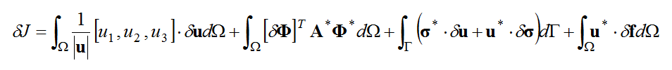
Assuming that small variations in the open area ratio (the design variable) will result in small variations in the pressure and velocity vectors of the convective field, the variation in the objective functional (its first variation, ) will be as follows.

Here, and
and are the components of the velocity vector,
 at each of the Cartesian coordinates, and
 is the differentiation operator matrix linearized around the convective field,(3). Taking the broad partial integral of the second term on the right of equation (14) splits the equation as follows into a regional integral and boundary integral.
Here, is the matrix formed from the adjoint operator for(3), and
 is the adjoint stress vector.
3.3. Adjoint Problem and Non-Parametric Sensitivity
To eliminate the regional integral term in equation (15) that includes the unknown variations, in the design space, equation (16) is selected as the adjoint problem.

Next, to eliminate the boundary integral term that contains the uncontrollable variations at the boundaries, namely, at the velocity boundary,
 andat the stress boundary,
 the following are selected as boundary conditions in the adjoint problem.


Doing so transforms equation (15) into the following boundary integral equation, which contains controllable variations only.

Therefore, the variations in the objective functional due to small variations in the boundary conditions and body force (the functional derivative) are given for the controllable boundary and throughout the region by equations (20), (21), and (22).


These give the non-parametric sensitivities which express the variations in the boundary conditions due to variations in the objective functional, and the adjoint problem equation (16) can be solved based on the boundary condition (17) and (18). It is also possible to use the pressure loss coefficient, to relate variations in the body force,
 to variations in the fluid resistance,
 and thereby to obtain the sensitivity to open area ratio from the relationship between the pressure loss coefficient,and open area ratio,
 . Equations (23), (24), and (25) express these relationships.


Here, and
and are the velocity and calculation mesh size respectively.
4. Numerical Calculation
4.1. Numerical Model and Boundary Conditions
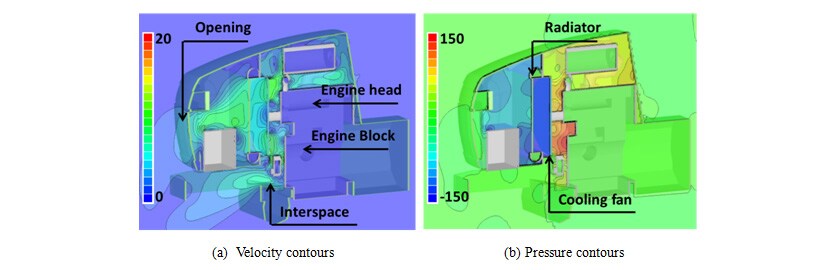
Fig. 2 shows the numerical model of the agricultural tractor. The engine room consists of the bonnet and ventilation openings composed with perforated metal. As shown in Fig. 2 (b), the cooling fan is located downstream side of the radiator. Other internal components are as shown in Fig. 2 (c).
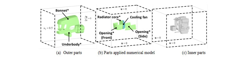
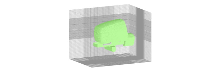
As shown in Fig. 2 above, the calculation boundaries are located on the six surfaces around the bonnet, with the front and rear boundary surfaces representing the inlet and outlet boundaries with air flow equivalent to vehicle speed respectively. The other four surfaces are treated as non-slip walls. Wall functions are applied to them. The openings at the front and side of the bonnet are modeled as pressure loss surfaces with an equivalent open area ratio of 59%. Similarly, the radiator core is modeled as a pressure loss surface with an equivalent open area ratio of 35%. The cooling fan is represented by specifying pressure flow characteristics for a disk-shaped surface. Because the bonnet and underbody are design variables that relate to open area ratio sensitivity, their wall surface conditions are not applied, and they are modeled as pressure loss surfaces with an equivalent open area ratio of 0.0001%. And, because the other component parts shown in Fig. 2 (c) above are not treated as design variables, their wall conditions are applied. As shown in Fig. 3, discretization is performed by the finite volume method using an orthogonal six-sided three-dimensional mesh. The pressure and velocity are linked using the SIMPLEC method, the standard k-ε model is used as the turbulent flow model, and the number of mesh elements is approximately 9,000,000.
4.2. Results of Direct Analysis
Direct analysis is performed to obtain the initial solution for the convective field,.FlowDesigner 10 from Advanced Knowledge Laboratory Inc. is used as the solver. Fig. 4 shows the calculation results. The flow into the engine room from the bonnet openings at the front of the vehicle travels around the battery and through the radiator, passes around the engine and other parts, and then exits the engine room through the openings in the side of the bonnet or other gaps interspace. Because the pressure loss occurs due to how the internal flow is shaped by the bonnet, if suitable bonnet opening positions can be determined, it should be possible to reduce pressure loss even if the area of the openings is small.
4.3. Results of Inverse Analysis
As described in section 2, the aim of the designers is to increase the mass flow of radiator cooling air,. Therefore, the location of the target region,is in front of the radiator core. The design variables (indicated by asterisks next to their names in Fig. 2 (a) and (b)) are the open area ratios for the bonnet, bonnet openings, radiator, and the underbody. That is, the pressure losses.
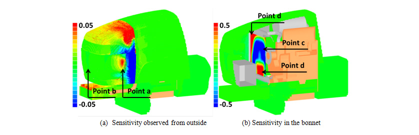
Fig. 5 shows the open area ratio sensitivities determined by inverse analysis performed using Flow Designer 10. Red zones indicate where the sensitivities are positively correlated with increases in cooling air mass flow,, whereas blue zones indicate where they are negatively correlated. High-sensitivity zones are present on the side of the openings at the front of the bonnet (“Point a” in Fig. 5 (a)) and on part of the top of the bonnet. Maximum sensitivity occurs on the radiator surface. This is because the pressure loss is comparatively large, whereas both positive and negative sensitivity are high. The zone with negative sensitivity (“Point c” in Fig, 5 (b)) is a vicinity of the cooling fan, and the zones with positive sensitivity (“Point d” in Fig, 5 (b)) are the four corners of the radiator and the rear of the battery. Because pressure losses are proportional to velocity, locations with high velocity have negative sensitivity suggesting that their open area ratios should be reduced and locations with low velocity have positive sensitivity suggesting that their open area ratios should be increased. Expressed from a different perspective, the results suggest that the wind velocity through the radiator should be equalized.
5. Inverse Analysis Results Verification with Design Changes
5.1. Design Changes
The radiator inlet coolant temperature,in the initial design is 84.4°C, meaning it has enough margin for overheating. Therefore, a part of openings were blocked in order to reduce noise. The non-parametric sensitivity analysis was then verified paradoxically by blocking high sensitivity and low sensitivity zones, and evaluating the cooling air mass flow,and radiator inlet coolant temperature,.
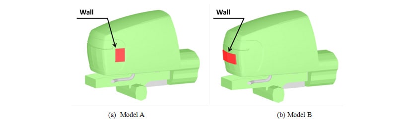
As shown in Fig. 6(a), air flow to the engine compartment was blocked by placing a wall with an open area ratio of zero in the vicinity of point a in Fig. 5(a), where openings in the bonnet have a high positive sensitivity. This configuration was designated “Model A”. Similarly, the same wall as used in Model A was placed in the vicinity of “Point b” in Fig. 5(a), where the open area ratio sensitivity is low. This configuration was designated “Model B.”
5.2. Calculation Results and Consideration
Direct analysis of Model A and Model B was conducted to compare the results before and after the design changes. Fig. 7 shows the mass flow rate of cooling air,and the pressure loss in the engine room. The mass flow,for Model A is 6.2% less than the initial design, and that for Model B is 1.3% less. Despite being blocked by the same parts, the reduction for Model A is 4.8 times that of Model B. Because the tendency in pressure loss is in the opposite to that of the mass flow,, the reduction in mass flow,can be attributed to the increase in pressure loss in the engine room associated with the shifting of the operating point of the cooling fan.
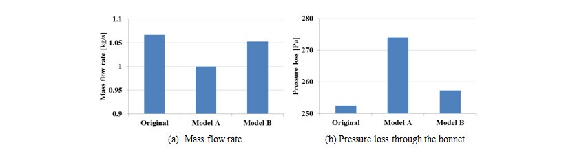
Fig. 8 shows the results of evaluating the mass flow of cooling air,and the radiator inlet coolant temperature,obtained by equations (7) and (8) for the models before and after the design changes. While the temperatures were higher for the two models with the design changes, the temperature was higher for Model A. Although both models have the same bonnet open area blocked with the same wall, the results show a 1.5°C difference in temperature the different location for blocking. This indicates the validity of the non-parametric sensitivity analysis results.

6. Conclusions
The following conclusions were obtained by a non-parametric sensitivity analysis for the thermal problems in the engine room of an industrial vehicle, in which the sensitivity analysis defined an adjoint problem that was linearized in the vicinity of the convective field for the initial design from the first variation of the objective functional for which the governing equation for the convective fields act as the constraint.
- (1)It is possible to obtain the design variable sensitivities by specifying the entire boundary
for open area ratio sensitivity without using a parametric method. - (2)It is possible to obtain the design sensitivities with a lower computational load
(two numerical calculations) than would be required for a parametric method. - (3)By considering changes in the objective functional and the physical situation, it was
verified that non-parametric sensitivity analysis produced suitable results for design
changes made to the engine room based on the calculated sensitivities. - (4)The proposed method offers a new way of obtaining design guidelines for thermal
management in industrial vehicles.
Acknowledgements
The author wishes to acknowledge his gratitude for the considerable assistance received from Dr. Kazunari Momose, a technical fellow at Advanced Knowledge Laboratory Inc., and Dr. Kaoru Ikejima, a director of that company. The author would also like to thank Megumi Nambu of the Technical Support Center of Yanmar’s Research & Development Center who created the geometry model used in the numerical calculation.
References
- (1)Shigeru Obayashi, “New Stage of CFD Application : Numerical Optimization”, Journal of the Japan Society of Mechanical Engineers, Vol. 105, No. 999 (2002), pp. 64-69 in Japanese.
- (2)Jameson, A., “Aerodynamic Shape Optimization Using the Adjoint Method”, Lecture Note at the Von Karman Institute (2003).
- (3)Momose, K. and Ikejima, K., “Optimization of Convective and Mass Transfer using Nonparametric Sensitivity Analysis”, Proceedings of 20th International Symposium on Transport Phenomena CD-ROM, No. 162 (2009).
- (4)Shuichi Nakagawa, Kazunari Momose, Kaoru Ikejima, “An Approach to Thermal Management in Engine Compartments of Industrial Vehicles Using Non-Parametric Sensitivity Analysis”, Transactions of the Japan Society of Mechanical Engineers Series B, Vol. 79 (2013), No. 805, pp.1774-1783 in Japanese.
-IMPORTANT-
The original technical report is written in Japanese.
This document was translated by R&D Management Division.
Author