Development Division
Large Power Products Operations Business
YANMAR Technical Review
Dual-Fuel Marine Engine (Highly Reliable Environmentally Friendly Engine)
Abstract
The growing demand to reduce engine emissions in recent years has led to interest in engines fuelled by natural gas, which can significantly reduce nitrogen oxides, sulfur oxides, particulate matter and carbon dioxide. This has led to recognition of the potential for marine engines fuelled by natural gas to help reduce marine environmental problems. This article describes the history, design, and technical characteristics of two-stroke and four-stroke dual-fuel engines, and considers the challenges and solutions to their use as marine engines.
1.Introduction(1)(2)(3)
To prevent air pollution from ships, regulations covering pollutants such as nitrogen oxides (NOX) and sulfur oxides (SOX) specified under the 1997 International Maritime Organization (IMO)/MARPOL Convention came into force in 2005 (Tier 1 regulations). These regulations were followed in 2011 by the Tier 2 regulations (a 15 to 22% reduction on Tier 1), with Tier 3 (an 80% reduction on Tier 1) to come into force for certain maritime regions starting from 2016. Similarly, to reduce greenhouse gasses (GHGs), the energy efficiency design index (EEDI) for CO2 emissions were introduced from 2013. This requires a 10% reduction in CO2 emissions by 2015 and a 20% reduction by 2020 (see Fig. 1).
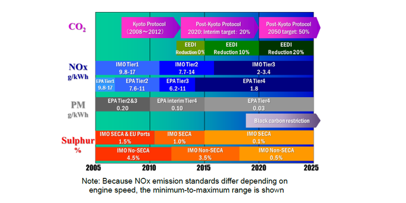
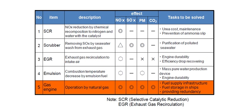
Fig. 2 shows a comparison of common engine technologies for reducing the exhaust emissions and GHGs from ships. The most important merit of fuel conversion to natural gas is that it is effective for reducing all exhaust emissions at once. This is in contrast to other technologies, each of which only works for certain exhaust emissions. This article describes the history, design, and technical challenges of dual-fuel engines designed for use in ships to improve their environmental performance.
2.History of Dual-Fuel Engines(4)
Gas engines have a very long history dating back to the invention, just 20 years after James Watt invented the modern steam engine in 1785, of a vacuum type piston engine that utilized coal gas combustion instead of steam. This is now recognized as the first-ever internal combustion engine.
Use of internal combustion engines spread rapidly after the Second World War when large amounts of cheap petroleum oil began to be produced in regions such as the Middle East. To make effective use of the natural gas produced by oil rigs as a byproduct of oil extraction, this led to the burning of the gas in diesel engines by mixing it with the intake air. This was the first example of a dual-fuel engine. Many different types of dual-fuel engines have been developed since then, many of which have been either diesel-ignited gas engines that use liquid fuel to ignite the gas fuel, or mixed combustion engines in which LNG tanker boil-off gas or the byproduct natural gas from oil extraction is used together with another fuel. While these types of dual fuel engines satisfied market demand when the objective was to utilize excess natural gas as a supplemental fuel, engines that use natural gas with the intention of reducing environmental impact must operate by using natural gas as much as possible.
Safety and redundancy requirements specified in ship classifications (see note 1) technical guidelines must be satisfied if natural gas engines are to be used on ships. That is, there is a need secure provision of backup for the case of gas-fueled operation being lost due to a problem in the fuel supply system or engine. Dual-fuel engines that are able to switch between gas and liquid fuel are recognized as satisfying this requirement.
Such switchable dual-fuel engines were first developed in the late 1990s as four-stroke engines. Practical two-stroke dual-fuel engines did not appear until 2010.
3. Basic Features of Gas Engines
3.1 Diesel Engine Combustion
Four-stroke diesel engines compress their intake air (or fuel mixture) by a ratio of between 1/14 and 1/16 and this increases the air temperature to between 300 and 350°C. Atomized diesel fuel is then injected into the compressed air causing it to react immediately with the surrounding oxygen, initiating combustion. The fuel burns locally, in almost the stoichiometric condition, and the high flame temperature promotes the oxidation of the nitrogen contained in the air. This is why the NOX levels for diesel combustion are so high.
3.2 Gas Engine Combustion
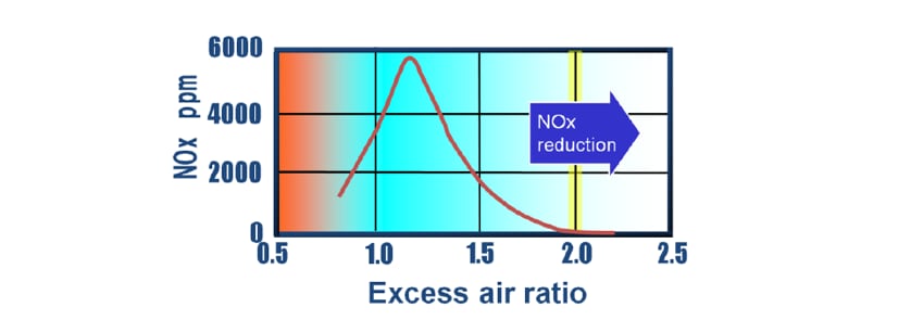
In the case of a gas engine, the high auto ignition temperature of natural gas means that combustion does not occur simply by injecting it into the compressed air. Accordingly, natural gas engines require an ignition source to initiate combustion. Generally, a spark plug or diesel fuel atomization is used to achieve this. In the case of a four-stroke engine, a pre-mixed homogeneous mixture of the fuel and air is introduced into the cylinder. Here, the formation of NOX can be reduced by using a pre-mixed fuel-air mixture with a leaner fuel-to-air ratio (excess air ratio (see note 2) > 1, meaning more air than is required by the stoichiometric ratio), because it results in a lower combustion temperature in the cylinder (see Fig. 3).
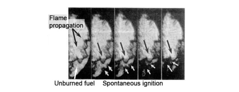
The way combustion should work in a gas engine is for the ignited flame to propagate through the unburned fuel mixture until combustion is complete. However, if the thermal load and combustion pressure in the cylinder increase for some reason, such as an increase in load, the unburned fuel mixture may ignite spontaneously prior to being reached by the propagating flame. If spontaneous ignition sets off a chain reaction, this can result in serious damage to the engine due to severe pressure or temperature increases. This type of combustion is known as knocking, and it is something absolutely to be avoided in gas engines (see Fig. 4).
Ways of avoiding knocking include reducing the compression ratio to reduce the compressed air temperature, and increasing the excess air ratio as high as possible (using a leaner mixture) to reduce the combustion temperature. However, reducing the temperature by too much may cause misfiring due to failure of the mixture to ignite. And because misfiring may result in fires due to unburned fuel mixture escaping into the exhaust pipe, it is something to be avoided.
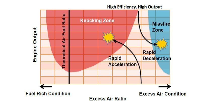
Fig. 5 shows gas engine combustion characteristics, where the horizontal axis represents the excess air ratio and the vertical axis represents engine output. Knocking occurs when output is high in the region where the excess air ratio is around one, whereas the region in which misfiring occurs is at higher excess air ratios. When developing a gas engine, the combustion conditions are selected so as to avoid the excess air ratio being in the regions where knocking or misfiring occur when operating under the expected load. However, when the load varies continuously, as is the case when used for ship propulsion, there is an increased risk of knocking or misfiring due to operation deviating from the target excess air ratio. In particular, because the inlet air flow depends on the speed of the turbocharger, the engine may fail to operate under load due to the turbocharger speed being unable to follow quickly to changes in load.
To achieve high output while aiming to keep the excess air ratio in the intermediate zone between the regions where knocking or misfiring occur, many recent gas engines incorporate mechanisms for adjusting the excess air ratio in accordance with operating conditions. Fig. 6 shows one such mechanism for adjusting the intake air flow. In addition to the main intake passage, it equips a bypass that returns some of the intake air to the turbocharger inlet. A bypass valve in the bypass closes under full load so that all the air discharged by the turbocharger is supplied to the engine, but it partially opens under partial load by adjusting valve opening angle to maintain the correct intake air flow to the engine.

4 Dual-Fuel Engines
4.1 Four-Stroke Dual-Fuel Engine
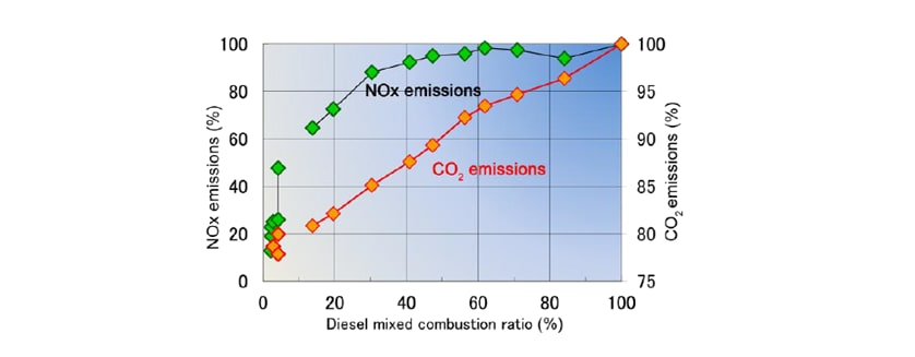
Gas fuel is supplied during the intake stroke of a diesel engine, and the exhaust emissions vary according to the proportions of diesel fuel and gas fuel in the total fuel (see Fig. 7). Because the concentration of CO2 in the exhaust gas depends on the composition of the fuel, it can be reduced by up to about 25% according to the proportions of diesel fuel and gas fuel. On the other hand, because the concentration of NOX depends on the combustion temperature, reductions in NOX can only be achieved by reducing the proportion of diesel fuel.
While achieving the IMO Tier 3 regulations (80% reduction in NOX) requires that the proportion of diesel fuel be reduced to 2%, no currently available nozzles are able to inject the full range of fuel injection quantities, from the amount required under rated load down to this very small quantity, in a reliable manner (without variation in the quantity injected for each cycle).To overcome it, adding a small dedicated nozzle (micro-pilot fuel injector) that supplies diesel fuel for the ignition when operating on gas fuel is necessary.
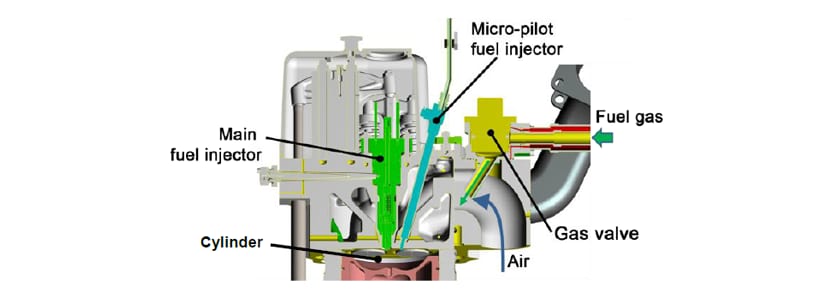
Fig. 8 shows a cross-section of a four-stroke dual-fuel engine. Gas fuel is supplied from a gas valve in the air intake manifold where it flows into the cylinder as a mixture with air. Two injectors, one is the main fuel injector used for diesel mode and another is the micro-pilot fuel injector used for gas mode, are equipped in the cylinder head, the engine can switch between diesel mode and gas mode freely with certain operating condition restrictions.
4.2 Two-Stroke Dual-Fuel Engine(5),(6)
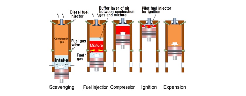
Because intake air is used for scavenging in a two-stroke engine, it is not allowed to mix the gas fuel with the intake air. Instead, the gas fuel is injected into the compressed air in the same way as diesel fuel, and then ignition is achieved by injecting fuel via the micro-pilot fuel injector (see Fig. 9). Because this results in diffusion combustion, as with diesel fuel, it can reduce CO2 emissions by 20% or more, with a low level of unburned gas and CO emission and without knocking. However, the level of NOX emissions is high due to the same reason.
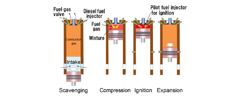
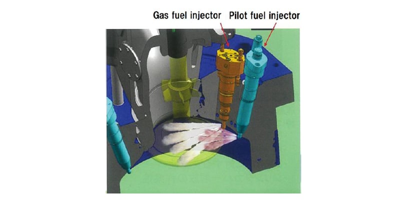
Fig. 10 shows the cylinder cover design for a two-stroke dual-fuel engine. In order to pressurize gas fuel injected into the compressed air up to 30 MPa, natural gas that has been pressurized in liquid form is vaporized and then injected into the cylinder. And because there is no risk of knocking, the switch between diesel fuel and gas fuel can be performed comparatively easily and quickly.
One proposal for improving the level of NOX emissions for two-stroke dual-fuel engines is to use a low-pressure gas fuel injection engine that can operate with a lean pre-mixed fuel mixture despite being a two-stroke engine. This involves using a fuel injection timing control method that enables the time delay of pre-mixing of gas fuel and air during the intake stroke described above that prevents the fuel-air mixture from coming into direct contact with the exhaust gas (see Fig. 11). Such an engine is currently under development with the aim of achieving low-NOX emissions similar to a four-stroke engine.
4.3 Control of Dual-Fuel Engines
Dual-fuel engines use an electronic controller for fuel flow control to enable switching between diesel mode and gas mode as required. In diesel mode, an actuator mechanically operates the fuel pump’s flow control lever, whereas in gas mode, the timing for opening the gas valve is controlled electrically with the energizing duration of time for an electromagnetic solenoid.
While it is possible to switch from gas mode to diesel mode by instantaneously shutting off the gas fuel and starting diesel fuel injection, switching from diesel mode to gas mode involves the engine speed control working through a procedure for transitioning from diesel mode to gas mode as the gas valve is slowly opened. This is because of restrictions on the range of the fuel-air ratios that can be used when operating in gas mode, which are dependent on operation condition such as the load or fuel characteristics, and the switchover is controlled automatically while monitoring for signs of knocking or misfiring.
The three main error modes in gas mode are knocking, misfiring, and gas leaks. Knocking can be detected by using a vibration sensor to find changes in combustion vibration or detected directly from the internal cylinder pressure waveform. If knocking is detected, the engine automatically adjusts its operation to prevent it. Although the usual practice is to reduce the maximum pressure in the cylinder by using the micro-pilot injector to delay the ignition timing, if this fails to halt the knocking, the operation automatically switches to diesel mode.
Misfiring can be detected from factors such as the exhaust gas temperature, internal cylinder pressure waveform, or engine speed fluctuation. If misfiring continues for a number of cycles without recovery, the operation automatically switches to diesel mode. Gas leaks are detected with a gas sensor. If a gas leak is detected, the gas valve is immediately shut off and the operation automatically switches to diesel mode.
4.4 Challenges for Dual-Fuel Engines
Because two or more different types of fuel are combusted in the same cylinder, one of the challenges for dual-fuel engines is lubrication. Whereas lubricants with high base numbers (30 to 40 mg KOH/g) are used when operating on low grade fuel (3.5% sulfur), lubricants with low base numbers (5 mg KOH/g) are used when operating on natural gas (0% sulfur). This is why the knocking margin would be reduced in natural gas fuel mode due to the build-up of alkalis deposit and other combustion deposit on the cylinder walls that act as a heat insulator causing the combustion temperature to increase. As a result, it can be difficult to select a lubricant for dual-fuel engines that will perform effectively with both diesel mode and gas mode.
Fuel characteristics are a problem specific to dual-fuel marine engines. Ocean-going vessels are supplied with fuel at their destinations (“bunkering”), but because the characteristics of natural gas differ depending on where it is produced, if a vessel takes on fuel with significantly different characteristics there is a risk for the engine to shut down due to knocking when it switches over to this new fuel. Currently though this problem can be overcome using particular operations such as restricting the range of fuels that can be used or limiting output, a challenge for the future will be to develop engine technology that can deal with different fuel characteristics.
5 Conclusions
Having emerged as a viable candidate for achieving environmental performance, future energy transformation, and the reliability demanded of marine engines, dual-fuel engines have come to be recognized for their potential for meeting the requirements imposed by society. However, number of unsolved problems and technical challenges still remain in the way of their use as marine engines, as a developer of engine technology, We keeps making efforts enabling the engines to achieve a level of maturity that will make them worthy of trust.
References
- (1)Eiichi Muraoka, “Recent Movement of International Rules Regarding air Pollution Prevention from Ships in the International Maritime Organization (IMO)”, National Maritime Research Institute 8, (2) 183 (2008) in Japanese.
- (2)“Energy-Efficiency-Related Treaties (EEDI and SEEMP)”, Nippon Kaiji Kyokai website in Japanese.
- (3)Kazuyoshi Harumi, “Tightening of Exhaust Gas Emission Regulations and How to Respond”, SEA JAPAN seminar documents, April 10, 2014 in Japanese.
- (4)Fumio Iwafuchi, “Historical Development of Gas Engine for Industry and Marine Use,” Center of the History of Japanese Industrial Technology, National Museum of Nature and Science in Japanese.
- (5)Takashi Watanabe, Shigeyuki Shibata, “Introduction of LNG Carrier Equipped with ME-GI Engine”, Journal of JIME, 49, (1) 13 (2014) in Japanese.
- (6)Takayuki Hirose, et al., “Development of 2-Stroke Gas Engine with Low Pressure Gas Injection”, Journal of JIME, 49, (1) 7 (2014) in Japanese.
- (7)Masaki Otsu, “Introduction to ME-GI LNG-Fueled 2-Stroke Gas Engine”, 2014 environmental seminar documents, Nippon Kaiji Kyokai in Japanese.
- Note 1:Ship classifications (ship classification societies) set technical standards for ships and equipment and confirm that designs satisfy the standards.
- Note 2:The stoichiometric proportion is the fuel-air ratio at which the fuel is fully combusted without any shortfall or excess, and corresponds to an excess air ratio of one. The excess air ratio becomes larger as the proportion of air increases.
◇This article is a reprint of an article that appeared in Vol. 38, Issue 3 of Petrotech, the magazine of The Japan Petroleum Institute.
-IMPORTANT-
The original technical report is written in Japanese.
This document was translated by R&D Management Division.
Author