Development Division
Large Power Products Operations Business
YANMAR Technical Review
The Technical Supports to Design the Cabin Noise more Comfortable
Abstract
Recently, the demand for a low noise environment in vessels has increased. Cabin noise typically arises from a number of different noise sources, including the engine, exhaust, fans, and pumps. In most cases, the primary source of noise is the engine.
Vibration isolating mount systems are usually effective at reducing structure-borne noise, especially in medium- and high-speed engines. This article describes the techniques Yanmar adopted in collaboration with a ship builder to reduce cabin noise in a well-known sight-seeing ship.
1. Introduction
The expected requirements for living environments of buildings such as hotels and hospitals is very high level these days and measures for preventing vibration and noise in on-site generation plants, in particular, extend beyond the power source itself to encompass the entire building, including vibration isolating mounts for the piping connected to engines and the use of low-noise ventilation fans.
In the marine industry, meanwhile, although noise prevention measures have been adopted on certain categories of vessels, such as luxury cruise liners and government-owned research vessels, there are also many categories of vessels in which noise reduction is made difficult by structural factors, such as the location of passenger cabins adjacent to an engine room or engine casing. However, with the introduction of noise regulation for the interior of vessels introduced by the International Maritime Organization (IMO) from July 2014 that extend strict noise restrictions to ordinary commercial vessels based on their international gross tonnage, noise minimization requirements will potentially become stricter in the marine sector also.
With reference to these developments, this article describes conventional measures for minimizing noise and examples of noise minimization measures used on a tourist vessel with a medium- and high-speed engine.
2. On-board Noise
2.1. Types of Noise Propagation
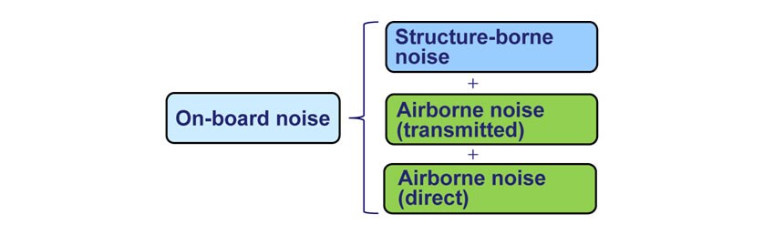
On-board noise can be broadly divided into two types depending on how the noise propagates. The first type is structure-borne noise that vibrations from the engine and ventilation fans propagate to the walls and floors through the structure of the vessel and the noise is radiated from them. The second type is airborne noise that radiates from a noise source and propagates via the air. Airborne noise can be further divided into transmitted noise, which passes through the structure of the vessel, such as the engine room bulkhead; and direct noise, which comes directly from the noise source.
Accordingly, the efficient reduction of on-board noise requires first identifying the contributory noise sources (machinery) considering the structural properties of the vessel, and then adopting countermeasures that take account of these properties.
2.2. Magnitude of Noise and Countermeasures
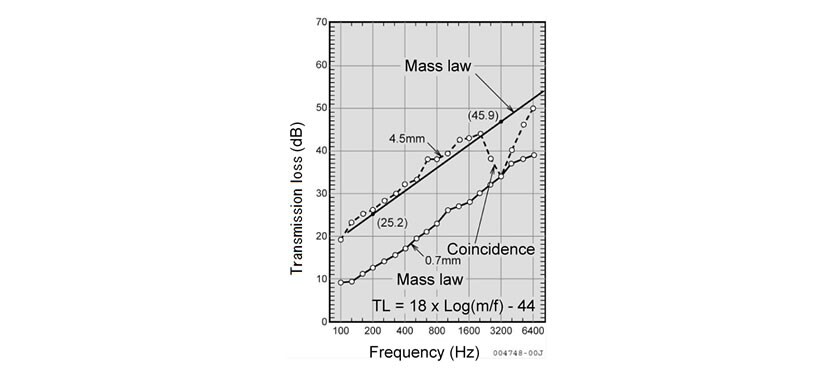
Apart from places such as open-deck passenger areas where there is a significant level of direct noise, there are bulkheads between cabin spaces and noise sources, and therefore airborne noise reaches such locations in the form of transmitted noise. As this noise is attenuated by the transmission loss of bulkheads (see Fig. 2), the contribution of transmitted noise to the noise level in cabin spaces is not large. In other words, while it depends on the target noise level, attempting to minimize cabin noise by reducing only airborne noise from the engine and other noise sources is inadequate in many cases.
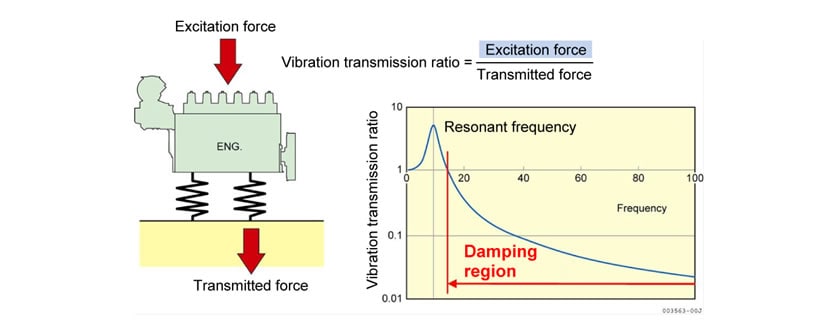
Based on experience, the largest contribution to cabin noise comes from structure-borne noise. As this noise is caused by the propagation of machinery vibrations, the measures to reduce it are by damping these vibrations. Typical noise reduction techniques include vibration isolating mounts or reducing measures for the machinery vibration, or changing the vibration propagation path. Fig. 3 shows example damping characteristics of vibration isolating mounts.
In the case of medium- and high-speed engines, because they operate at higher rotational speed than that of low-speed engines, it is easy to select vibration isolating rubber mounts having the natural frequency lower than the frequency of the major excitation force of the engines.
Accordingly, use of vibration isolating mounts is an effective measure for most vessels, and it is an advantage of medium- and high-speed engines that vibration isolating mounts can be used for reducing on-board noise.
3. Example Measures for Reducing On-Board Noise
3.1. Vessel
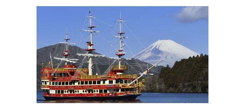
Measures for reducing on-board noise were introduced on the Royal II, a sight-seeing ship that has been operated by Hakone Sightseeing Cruise Co., Ltd. on Lake Ashi since March 2013.
- Owner:
- Hakone Sightseeing Cruise Co., Ltd.
- Shipyard:
- Japan Marine United Corporation
- Engine:
- Yanmar Co., Ltd.
Main engine (with vibration isolating mounts): 6HYP-WET,
Main generator engine (with vibration isolating mounts): 6HAL2-WT - Dimensions of the vessel:
- overall length 35m, overall breadth 10m
3.2. Countermeasures Adopted
The main countermeasures adopted were as follows, and thanks to the thorough work of Japan Marine United Corporation, the predicted effect of noise reduction was achieved.
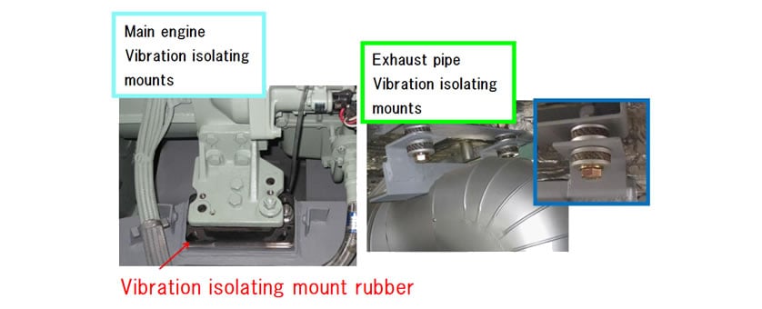
- Vibration Isolation mounts for the medium- and high-speed main engine and main generator engine
- Vibration Isolation mounts for exhaust pipes
- Vibration Isolation mounts for main generator cables
- Installation of vibration damping steel sheets on engine room walls
3.3. Noise Reductions
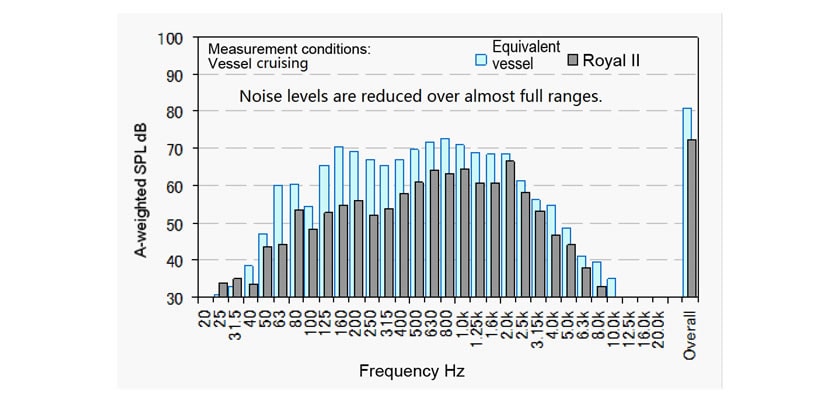
A comparison with noise levels measured at the same location (lobby immediately above the engine room) on another Hakone Sightseeing Cruise ship with a main engine installed directly to the hull, but otherwise of near-identical design to the Royal II, found that the countermeasures reduced noise by approximately 10 dB when cruising.
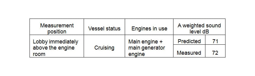
Based on existing knowledge and detailed measurements of vibration noise on the other ship with similar shape and size, a predictive calculation was made of the likely noise reduction that would result from the planned countermeasures, including the vibration isolating mounts for the main engine. Table 1 lists the calculation results, which are in good agreement with the measured noise to within one dB.
Table 1. Predicted Results of Noise Reduction
4. Conclusions
Yanmar would like to take this opportunity to express its gratitude for the accomplishments made possible by the generous support and advice provided by Hakone Sightseeing Cruise Co., Ltd. and Japan Marine United Corporation.
The issue of vibration noise in cabin spaces is an ever-recurring environmental problem. Although a steady stream of new measurement instruments and improved products are becoming available on the market, there have been no major changes in the analytical techniques and problem solving approaches that form the basis of countermeasures.
Major advances in analytical and predictive techniques can be anticipated as demand for noise reduction becomes more apparent in the marine market. These advances will likely be accompanied by an accumulation of know-how about how to reduce vibration and noise. Yanmar intends to continue working on this problem.
-IMPORTANT-
The original technical report is written in Japanese.
This document was translated by R&D Management Division.
Author

Japan Marine United Corporation