Development Division
YANMAR ENERGY SYSTEM CO.,LTD.
YANMAR Technical Review
Development of High Efficiency BP-G 300kW-Class Biogas Co-Generation System
Abstract
The BP-G is a high efficiency biogas co-generation system designed to operate on biogas with a methane concentration of 55 to 65% produced from sewage sludge or food waste. The BP-G has an output of either 275kW (50Hz systems) or 325kW (60Hz systems), an efficiency of 37.0%, and NOX exhaust emissions of less than 600ppm.
High efficiency and reliability are achieved through the following features:
① Use of an existing high-performance Yanmar gas engine modified to operate on biogas
② Stable and best performance despite fluctuation of volume and composition of biogas
③ Highly reliable electronic control system already proven in existing EP-G (natural gas) systems
1.Introduction
While use of gas engine co-generation systems has grown for reasons of effective energy utilization, CO2 emissions reduction, and better economic performance, since the Great East Japan Earthquake of 2011 the systems have also been called on to support electricity saving, peak cutting, security of electric power supply, better business continuity planning (BCP), and distributed energy system(best mix).
Renewable energy is one form of distributed energy system. With a feed-in tariff (FIT) scheme for renewable energy being introduced in Japan in July 2012, and a cabinet decision in June 2015 setting a government target of increasing the proportion of electric power generation from renewable energy to between 22 and 24% by FY2030(1), there are high expectations for growth in the market for biomass generation. This article describes the BP-G, a high efficieny300kW-class gas engine co-generation system specifically designed to burn biogas that was developed by Yanmar with the aim of stabilization of this sort of social infrastructure and realization of resource recycling society.
2.Development Background
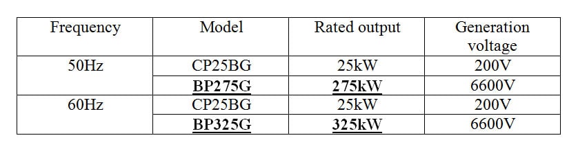
For the biogas market, Yanmar Energy Systems has already released the 25kW-class CP25BG (50Hz and 60Hz) micro gas co-generation systems listed in Table 1, of which more than 500 have already been installed (as of FY2015). Together with this CP range, Yanmar has embarked on developments aimed at establishing itself as the market leader for biogas power generation systems in Japan, having expanded the range of outputs it is able to supply by developing and launching the new BP-G series of 300kW-class (275kW in 50Hz regions, 325kW in 60Hz regions) generators.
In terms of performance, the systems are designed to contribute to reducing environmental load by delivering a high level of generation efficiency to ensure that good use is made of biogas (55 to 65% methane concentration) given off by sources such as sewage sludge or food waste, while also maintaining stable operation despite the fluctuation of calorific value that is characteristic of biogas. To improve the security of electric power supply, the system is also designed for robust performance so as to ensure stable power supply by reducing the frequency of system outages.
Table 1 Biogas Co-Generation System Product Range (as of May 2016)
3.Biogas Co-Generation Systems
3.1.Conversion of Biomass Energy
Fig. 1 shows an overview of how biomass is converted into biogas.
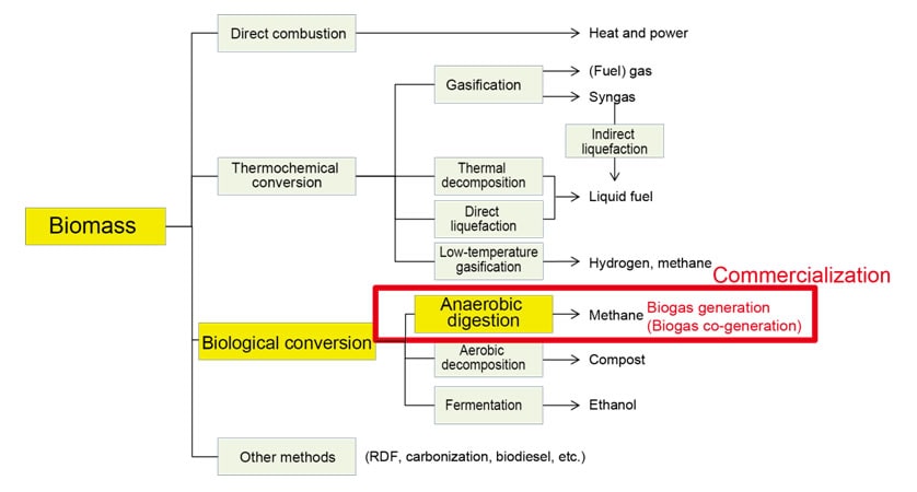
Biomass means a resource obtained from a biological source. As shown in Fig. 1, a wide variety of methods are available for converting biomass into energy. Examples include direct combustion whereby a fuel such as wood pellets is directly burnt to produce heat and electricity, thermochemical conversion whereby heat is used to convert biomass into liquid fuel or gas that can be used as a source of energy, and biological conversion whereby microorganisms are used to transform biomass into methane or other fuels. One common form of biological conversion is anaerobic digestion whereby the action of methanogens produces methane (with feedstock such as sludge at sewage treatment plants or waste at food processing factories providing the biomass). The new BP-G system is fueled by methane gas produced by this conversion process.
3.2.Flowchart of Biogas Co-Generation System
Fig. 2 shows a system flowchart of biomass to biogas co-generation.
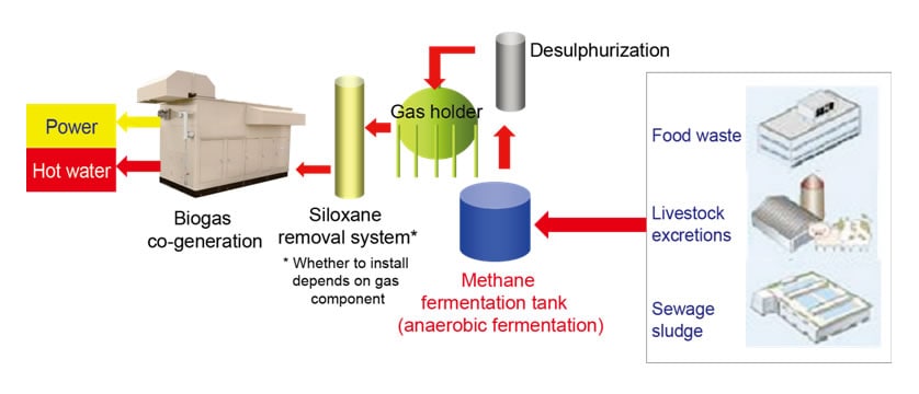
As noted in section 3.1 above, the biomass is provided by feedstock such as food waste or sludge at sewage treatment plants. The materials, which is placed in a tank where fermentation is used to produce methane gas. However, because this methane also contains contaminants such as hydrogen sulfide and siloxane that are detrimental to the co-generation system, these must first be removed. The fuel production process is equipped with desulphurization and siloxane removal systems to ensure that the system has the reliability and durability to prevent interruptions to co-generation operation.
4.Product Development (Product Features and Technologies Adopted)
4.1.Appearance and Main Features of BP-G
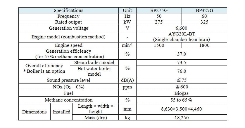
Fig. 3 shows an appearance of the BP-G, Fig. 4 shows the internal layout, and Table 2 lists the main features.
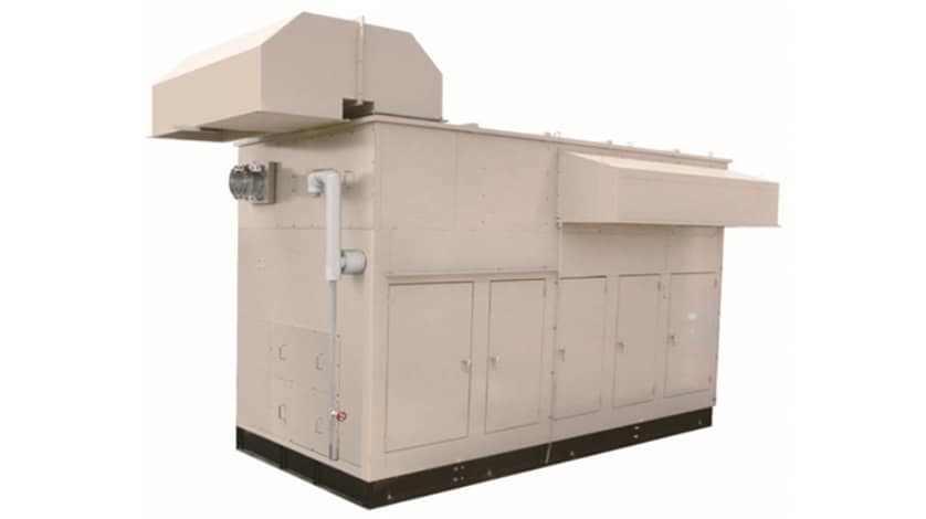
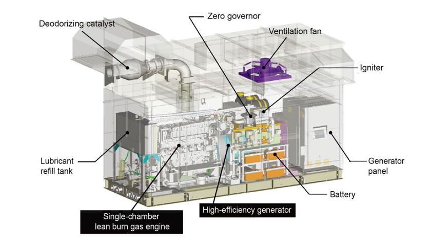
Table 2 Main Features of BP275G (50Hz) and BP325G (60Hz)
The BP-G power generation system is made up of a generator driven by a biogas-fueled gas engine. It achieves a generation efficiency of 37.0% using a fuel (55 to 65% methane concentration) with a very low calorific value (19.7 to 23.3MJ/Nm3). In its optional boiler specifications, the BP-G can also achieve a high overall efficiency by recovering thermal energy from the exhaust gas and engine cooling water. NOX emissions are within the 600ppm (for O2=0% conversion) requirement of Japan's Air Pollution Control Act. All system components are placed in the same package, including the gas engine, generator, cooling water and other pumps, heater, ventilation fan, and generator panel (which controls them).
4.2.Technologies for Using Biogas as a Fuel (Gas with Low Calorific Value)
Fig. 5 shows the AYG20L-BT gas engine and the gas fuel control devices (throttle, gas mixer, fuel flow control valve, and zero governor) installed in the BP-G package, together with the technical issues and how they are dealt with.
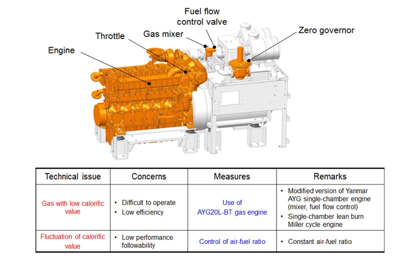
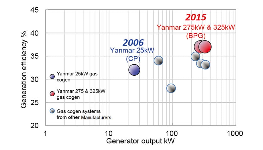
The two main technical issues associated with using biogas are its low calorific value (making the engine difficult to operate, with low efficiency) and the fluctuation of the calorific value (resulting in low followability for performance). To solve the first issue of low calorific value, the AYG single-chamber lean burn Miller cycle gas engine that the Power Solution Business of Yanmar already sells outside Japan was adopted as a base due to its proven performance and modifications made to the device specifications of the mixer and fuel flow control valve. Thanks to engine performance matching to improve efficiency, the BP-G achieves a generation efficiency of 37% which places it among the best biogas co-generation systems on the market, as shown in Fig. 6 (see red dots on graph).
The second issue of calorific value fluctuation is overcome by means of engine control using the fuel flow control valve to control the fuel-air ratio. Fig. 7 shows an overview of how engine control works.
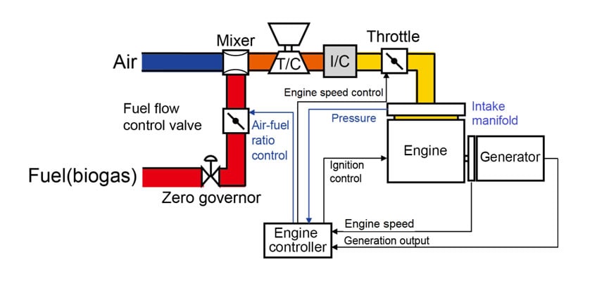
The biogas is supplied through the fuel flow control valve to the mixer where it is mixed with air. The fuel-air mixture is then compressed in the turbocharger (T/C) and charged into the combustion chamber, after its amount is controlled by the throttle using engine speed feedback control.
Fuel-air ratio control is performed by operating the fuel flow control valve under feedback control to maintain the specified intake manifold pressure at the engine inlet according to the generation output.
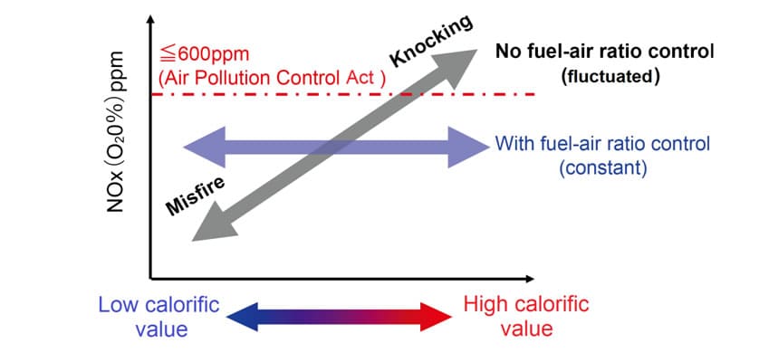
As shown in Fig. 8, without fuel-air ratio control, the variation of calorific value of the biogas causes fluctuations in the NOX concentration in the exhaust gas and makes the engine easy to misfiring or knocking (indicated by the dark arrow in the figure). In contrast, fuel-air ratio control provides stable engine operation, with the level of NOX concentration remaining constant despite fluctuations in calorific value (indicated by the blue arrow in the figure).
4.3.Optimum Control of Number of Operating Generators Based on Biogas Availability by the combination of CP units
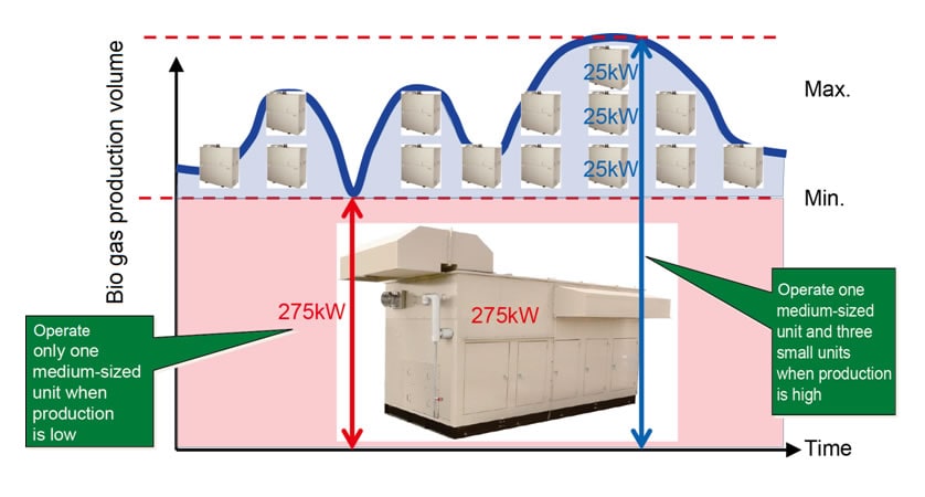
Fig. 9 shows how co-generation units operate according to the production volume of biogas. The biogas production volume fluctuates due to factors such as ambient temperature and feedstock amount. If a single co-generation system sized to cover the maximum biogas production volume is used, the problem of low power generation efficiency may occur because it operates at partial loads for a long period of time. In contrast, a system configuration that combines BP-G and CP25BG units can keep co-generation in an efficient operating range by, for example, operating a single BP-G only when biogas production is low but BP-G and multiple CP25BG units when production is high.
4.4.Application of Advanced Control System and Service Tool Proven in Current EP-G
For a control system and an in-market service tool, the BP-G features the same proprietary control system that has proved highly reliable in Yanmar's current EP-G series models (EP370G, 400G, 700G, and 800G). This achieved to reduce the time and cost of development for the 300kW-class BP-G model for the biogas market while ensuring its reliability.
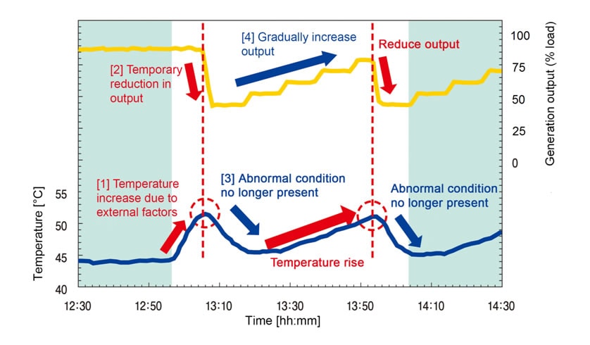
(1) Use of output-limiting to prevent serious failures (function for de-rating when temperature rises)
An issue with systems with a generation output in the 300kW range is the greater risk of users being charged penalties for exceeding their contracted level of electric power use due to unexpected shutdowns (stop with a serious failure) in power generation. Same as the existing EP-G series, the control logic used on the BP-G sets a number of major failure items and, rather than immediately shutting down operation, keeps the system operating at a level where there is no serious influence to the engine. Fig. 10 shows the results of a test that simulated this control operation. One such example is a temporary rise in the temperature of system components on a hot day in summer. In this case, the control system responds to certain conditions by reducing output for a time to avoid any risk to the engine, then gradually increases output once the temperature has dropped. The control can minimize unplanned system shutdowns.
(2) Support for In-Market Servicing
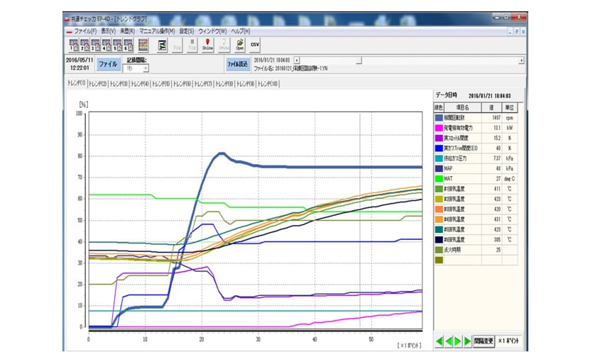
A version for the BP-G has been added to the existing tools used by customer support staff for onsite monitoring of system measurement values and recording them. Fig. 11 shows an example screen. This helps speed up on-site troubleshooting and control system monitoring, and is used in conjunction with 24-hour remote monitoring from a remote support center to provide better customer support.
5.Conclusions
As described in this article, the BP-G biogas co-generation system helps deliver greater life cycle value (LCV) to customers, including use of renewable energy, high efficiency, lower CO2 emissions, and greater security of electric power supply. We believe that this wider adoption of co-generation can contribute to the objectives embodied in Yanmar's mission statement of, "focusing on the challenges customers face in food production and harnessing power, thereby enriching people's lives for all our tomorrows."
References
(1) Ministry of Economy, Trade and Industry, "Long-Term Energy Supply and Demand Outlook", published on July 16, 2015
-IMPORTANT-
The original technical report is written in Japanese.
This document was translated by Research & Development Management Division.
Author