Research & Development Center
Research & Development Unit
YANMAR Technical Review
Use of Model-Based Techniques for Marine Engine Development
Abstract
This article describes the development of an engine test bed system that simulates actual marine vessel behavior. The test bed system calculates vessel velocity and propeller load based on the equations of motion for the marine propulsion system. The calculated load is then used by the system to control the load on the engine, thereby simulating actual operating conditions. The results from actual vessel tests were used for calibration to determine the system parameters in the motion equations.
Two example applications of the test bed system to marine engine development are described. One is the calibration of transient boost compensation to find out the best condition satisfying acceleration and smoke. Another is an injection control function that minimizes smoke at the initial stages of acceleration.
The article concludes with a discussion of the importance of conducting testing under conditions that engines will encounter in practical use, and the key role of model-based development in achieving this.
1.Introduction
The engine speed, load, and other operating conditions for marine engines vary widely depending on the use and specifications of the vessels in which they are installed. However, because of the difficulty of performing on-bed test covering all specifications at the development stage, generally typical marine propeller load pattern including cubic law or 2.5 power law load are used. While these load patterns can, to a certain degree, simulate actual behavior of the vessel under steady cruising conditions, they tend to underestimate the load in other cases such as semi-planing (hump) or acceleration, making accurate evaluation and power matching difficult. In the case of pleasure boats in particular, direct feelings of acceleration responding to accelerator operation and no smoke during acceleration are important aspects of product quality, and a high level of power matching during engine development is desirable. With these backgrounds, in this work a virtual evaluation system that simulates engine conditions in an actual vessel on the test bed was created. This article describes an example that the system was utilized in the development of a marine engine.
2.Vessel Model and Test Bed System
2.1.Vessel Model
(1) Basic equations
The basic equations for the vessel model consist of the motion equation of the vessel (1) and the propeller shaft and other rotation parts (2)(1)(2), as shown below.
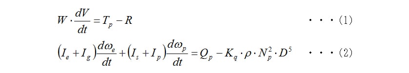
 :Vessel mass [kg],
 :Vessel velocity [m⁄s],
 :Propeller thrust [N],
 :Vessel resistance [N]
 :Inertial mass of engine, marine gear, shaft, and propeller [kgm2]
 :Rotational angular velocity of engine and propeller [rad⁄s]
 :Propeller torque [Nm],
 :Torque coefficient [-]
 :Density of seawater [kg/m3],
 :Propeller rotational speed [1⁄s],
 :Propeller diameter [m]
The propeller thrust in equation (1) is expressed as follows (3):

 : Thrust coefficient [-],
  : Thrust deduction coefficient [-]
The engine speed  and propeller rotational speed
  are related by the gear ratio
  of the marine gear. This is expressed as follows:

Here,  is a coefficient that represents the clutch slip characteristics (clutch coefficient), with a value in the range 0 to 1.
(2) Propeller characteristics
The thrust coefficient  and torque coefficient
  eferred to above represent the indexes of the propeller in open water. Fig. 1 shows typical characteristics. In this work, both characteristics are assumed to be a first-order function of the propeller advance ratio J and are modeled as shown by formulas (5) and (6).
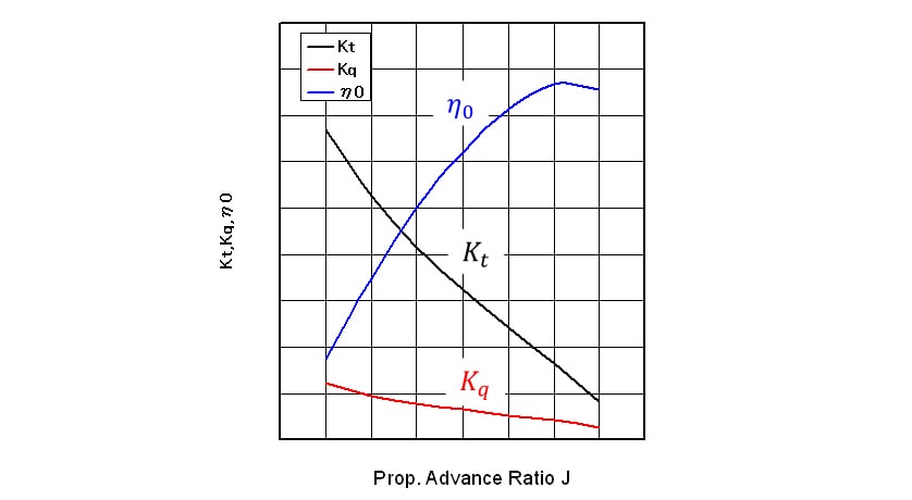

The propeller advance ratio J is defined as follows:

Here,  is the wake coefficient and represents a value found by dividing the seawater velocity, which is dragged by the hull and flows in the same direction of and around the vessel by vessel velocity
  .The wake coefficient depends on the hull shape and the cruising conditions.
2.2. Test Bed System
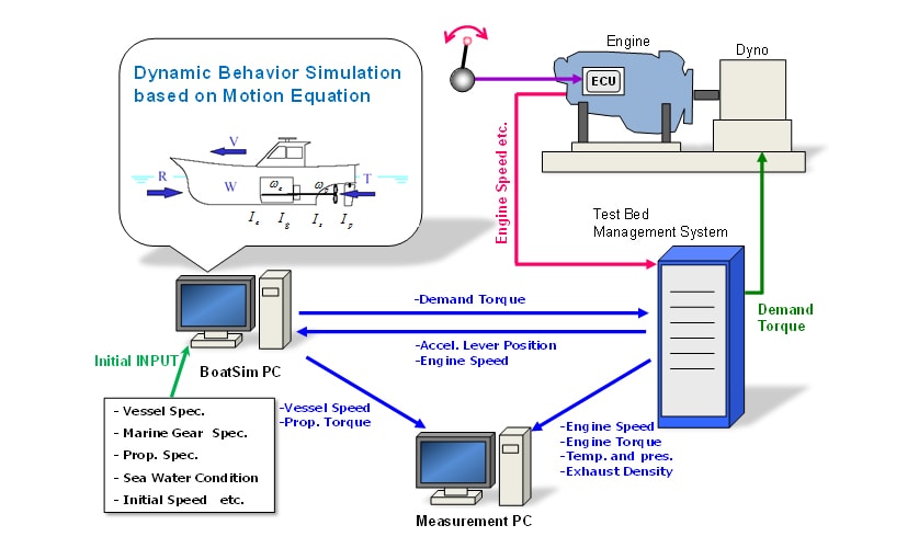
Fig. 2 shows a schematic diagram of the new engine evaluation system on the bed. The engine under test is coupled directly with an alternating current dynamometer (Meidensha, THYFREC VT310DY) without a marine gear. The test bed control system that controls the dynamometer was retrofitted with a PC for simulating the actual vessel behavior in addition to standard engine performance test functions. The PC analyzes the equations of motion for the vessel and rotation parts on MATLAB/Simulink to compute the vessel velocity and propeller load of the virtual vessel based on real-time input of accelerator position and engine speed. The engine can be loaded with the demand absorption torque equivalent to the actual vessel load, which is transferred to the test bed, calculated using the computed propeller load.
2.3. Simulink Model
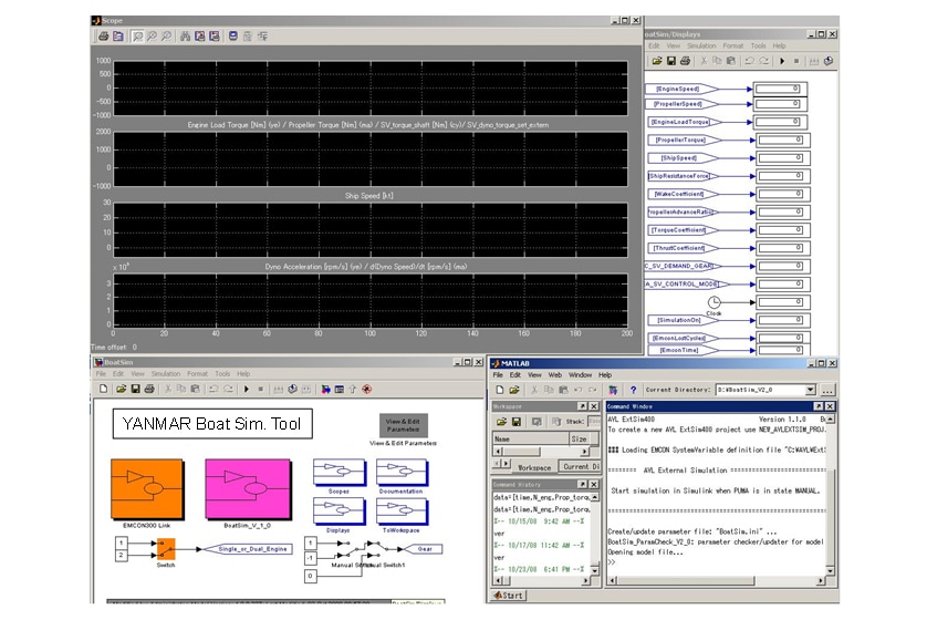
(1) Main window
A Simulink model was developed to estimate the behavior of the vessel based on the equations of motion described in section 2.1 above. Fig. 3 shows the main window of the test bed system.
(2) Determination of system parameter
The test bed system parameters are determined using an actual test vessel as a model. Details are described below.
① Clutch slip coefficient 
As the scope of testing only includes the vessel under steady cruising and acceleration conditions, no clutch slip is assumed and then =1.
② Wake coefficient
As the right hand side of equation (2) is equal to zero under the steady cruising condition, it can be rewritten as equation (8) and then, can be obtained by measuring , and on the actual vessel test under the steady cruising condition.

③ Vessel resistance and thrust deduction coefficient
The vessel resistance R for an actual vessel depends on factors such as hull shape and wave condition. The thrust deduction coefficient , meanwhile, is difficult to model because it is affected by the presence of cavitation around the propeller. For this work, a thrust deduction coefficient of 0.2 was chosen for simplicity(3), and the vessel resistance was calculated using equations (1) and (3) based on data from the model vessel under steady cruising conditions.
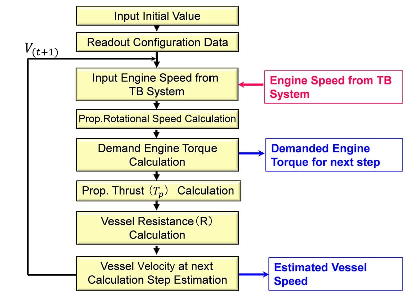
(3) Flowchart
Fig. 4 shows the flowchart of the vessel behavior simulation. When the test starts after loading the initial conditions, the engine speed is read continuously and the demand engine torque is calculated, and it is transferred to the dynamometer load via the test bed system. The current propeller thrust and vessel velocity are used to estimate the velocity and resistance of the vessel for the next time step. By repeating this calculation continuously, the propeller load which simulates the vessel cruising conditions can be provided to the engine test bed.
3.Examples of Application to Engine Development
This section describes examples of the application of the new test bed system to the development of a marine engine. The balance between vessel acceleration and smoke is a particularly important criterion for marine engines. However, the vessels in which these engines are installed come in a variety of shapes and sizes, and the performances are also influenced by the selection of marine gear ratio and propeller dimensions. This makes it difficult to determine a unique load curve. In contrast, continuous quantitative measurements of smoke on the actual vessel test are difficult and it is also extremely difficult to collect reliable data under conditions in which the wind direction, wind velocity, and tidal current are continually changing. The newly developed test bed system can evaluate the engine performance under a wide variety of vessel and operating conditions simply by changing the vessel specifications. The bed test also allows to measure transient performance and smoke accurately.
The engine selected for testing was a 6CX530 (displacement: 7.4L, bore and stroke: 110mm×130mm, 390kW/2900min-1), and the model vessel for the virtual system was a 36-foot test vessel (INIFINI36) installed with two 6CX530 engines with dual shafts. Data was collected from the vessel under steady cruising conditions prior to the bed test, and this was used to determine the system parameters for the Simulink model described in section 2.3. The following describes an example of how the test system was used for the development of engine control.
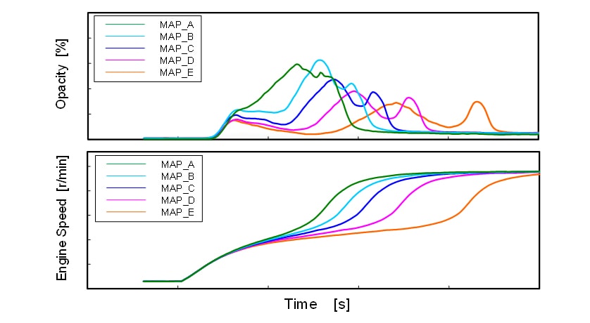
3.1. Calibration for Transient Boost Compensation
Boost pressure compensation function prevents the generation of smoke from a marine engine during acceleration by limiting the fuel injection quantity based on the boost pressure. Fig. 5 shows a calibration example of using boost compensation on the test system. The figure shows a comparison of characteristics of five boost pressure compensation "maps" (A, B, C, D, and E). Map A places maximum priority on acceleration performance and has the fastest acceleration time, but also high smoke density (opacity). Map E, in contrast, is oriented minimum smoke density, and the result is that almost no smoke is visible, but the acceleration time is approximately twice as slow as Map A. In this way, optimum acceleration performance for the actual vessel can be achieved by using the most suitable one within several maps which consider different specifications and are calibrated by the test system beforehand.
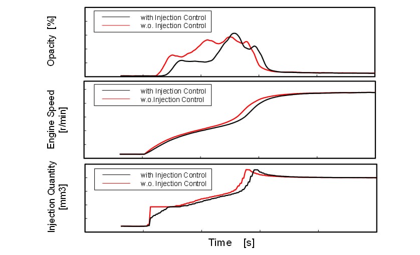
3.2. Evaluation of Fuel Injection Quantity Control during Initial Acceleration
When the accelerator is rapidly moved to maximum position during slow moving of a vessel, the engine may momentarily emit a high density of smoke during the initial acceleration. This is believed to be caused by an excess of fuel being supplied when the engine is at low speed and quantity and movement of air in the cylinder is insufficient. To minimize the smoke during initial acceleration, a function has been created that forcibly controls the initial quantity of fuel being injected when it is judged from the accelerator position and engine speed that the engine is under acceleration.
Fig. 6 shows an example of this function being verified on the test system. The black and red lines in the figures show the results when the function is used and is not used respectively. As the figure indicates, reducing the injection of fuel during initial acceleration minimizes smoke without impairing the vessel acceleration characteristics to any great extent.
4.Conclusions
This article has described the development of a system that enables an engine test bed to simulate the behavior of an actual vessel, and results obtained by using the system. While the new test bed system makes it possible to perform testing during engine development under more realistic conditions, it has yet to achieve adequate simulation accuracy. The wake coefficient w, thrust deduction coefficient t, and vessel resistance R, for example, are governed by complex mechanisms, and are not believed to be represented by the current logic sufficiently. Furthermore, the current work deals only with straight movement whereas there are various other modes of vessel operation to be evaluated, including clutch engagement and disengagement, crash astern, and maneuvering. More intensive understanding and modeling of the behavior and characteristics of the hull and propeller are likely to be needed before all of these operations can be simulated on a test bed.
Looking circumstances surround engine development, the new Real-Driving Emissions (RDE) regulations being adopted by European vehicle manufactures requests to evaluate exhaust emission and fuel consumption under actual operating conditions. In the case of off-road engines also, there is likely to be an increasing focus on their fuel consumption and exhaust emissions under the conditions that engines are installed in various working machinery or vessels. To satisfy these requirements, there is a need to improve technologies of ensuring that Yanmar engines achieve not only standalone performance but also deliver optimum performance under the conditions in which customers actually use them. Model-based development (MBD) techniques such as the one described in this article are the key to achieving this. By further enhancing MDB techniques, Yanmar intends to develop technologies that will not only achieve "Best energy with the minimum impact on the environment", but also deliver the best possible Y-Experience.
Finally, the author would like to express their thanks for the considerable assistance provided during this work by Kazuhiro Yamada and Hiroshi Tanaka of the Large Power Products Management Division, Power Solution Business.
References
- (1)Carton: Marine Propellers and Propulsion (2nd Edition), Butterworth-Heinemann, 2006, p.79-85
- (2)Masaru Ikeda, "Design and Drawing of High-Speed Boats", Kaibundo, 1978, p.66-136
- (3)MIT Open Course Ware. "Maneuvering and Control of Marine Vehicles",
http://ocw.mit.edu/courses/mechanical-engineering/
-IMPORTANT-
The original technical report is written in Japanese.
This document was translated by Research & Development Management Division.
Author