Development Division
YANMAR ENERGY SYSTEM CO.,LTD
YANMAR Technical Review
New 35kW Gas Micro Cogeneration System with Easier Indoor Installation and Higher Energy Efficiency
Abstract
Gas engine cogeneration systems provide electric power and waste heat for uses such as hot water and air conditioning. Yanmar Energy Systems Co., Ltd. launched its first compact 9.8kW system in 1998 and has since expanded its product range. In particular, Yanmar products helped customers save energy and power during the power shortages that followed the Great East Japan Earthquake.
Recent years have seen growing demand for the replacement of indoor systems installed 10 to 20 years ago. This has created a need for co-generation systems that are easy to transport and take up less space, and also for better energy saving performance.
This article describes the new CP35D1 that features easier indoor installation and higher energy efficiency.
1.Introduction
Gas engine cogeneration systems use a gas engine to generate electric power and save energy by utilizing the waste heat from the gas engine for heating and cooling or the production of hot water.
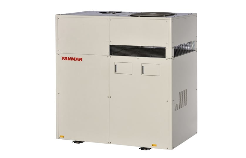
The features of the small cogeneration systems from Yanmar Energy System Co., Ltd. include high generation efficiency achieved by using a high-frequency permanent magnet generator in combination with an inverter for grid connection, and that they are supplied as a compact all-in-one package that also includes a heat exchanger for hot water production and a radiator for heat release. Since the YCP9800 (with a 9.8kW power generation) was first launched in 1998, the product range has been expanded by the addition of 5kW, 25kW, and 35kW models and an extensive range of variations, with the introduction in 2006 of a model designed to improve security of supply that prioritizes the supply of electric power to selected loads in the event of a grid power interruption. As a result, the systems have been adopted by customers in a variety of industries, including welfare facilities, hospitals, restaurants, shops, and factories.
This article describes the overview and features of a new 35kW model (model name: CP35D1) that includes additional product enhancements over the previous 35kW model (the largest available power generation).
2.Background to Development
With the power shortages that followed the Great East Japan Earthquake, recent years have seen growing interest in cogeneration as a way to help the need for both energy efficiency and power saving, with increasing demand both from new projects and for the replacement of existing medium-sized systems with power generation in the 100 to 200kW range that were installed 10 to 20 years ago.
As most of these systems are installed indoors, ease of transportation and installation space considerations meant that the existing model (model name: CP35VC) was too large.
There was also demand from customers for cogeneration systems with better energy efficiency.
Given these background factors, a new model was developed with the aims of making systems more energy efficient and easier to install indoors.
3.Product Features
The CP35D1 was made 27% (300 mm) narrower in the depth direction than the previous model so that it would be easier to transport to indoor sites and require less space for installation. The component layout of the upper part was also modified to make the system easier to transport in disassembled form.
To improve energy efficiency, the ratio of heat recovered from the engine was increased to 54.5% (3.5 percentage points higher than the previous model) with overall thermal efficiency of 88%, placing it in the top class of small cogeneration systems.
Furthermore, to reduce the amount of work required for ventilation of the machine room when installed indoors, the new model was made available in a variant without a radiator.
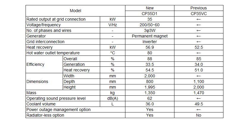
Table 1 Comparison of System Specifications
4.Overview of Development
4.1.Improvements to Ease of Transportation and Installation
4.1.1.Reduction in Package Size
To make the system easier to transport, the development target was to make it narrower in the depth direction than the standard access door width while still having the same or smaller width dimension as the previous model to allow for replacement installations. To achieve this target, Yanmar set about miniaturizing those components that took up a large amount of space in the previous model. Specifically, this involved the following changes.
(1)Downsizing of engine
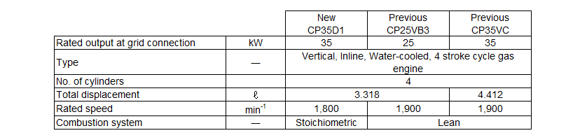
Because there was a limit to how much narrower the previous engine could be made in the depth direction, a new version of the 25kW engine with a higher output was developed to enable downsizing. Whereas the previous model had used lean combustion, this was changed to stoichiometric combustion for the new engine. In contrast to lean combustion, which supplies more than the theoretically required volume of air to the cylinder, stoichiometric combustion needs only the theoretically required volume of air and therefore is able to supply more fuel to be burned in the cylinder. This enabled the combustion chamber pressure to be increased and the generation power to be increased to 35kW while keeping the engine size the same as the 25kW model (see Table 2).
Table 2 Comparison of Engine Specifications
(2)Simplification of exhaust system
Two of the components fitted on the previous model were a silencer to reduce engine exhaust noise and a mist separator to remove water droplets from the exhaust gas. These components are major determining factors in the package size because they have to be large enough to cope with the volume of exhaust gas. To reduce the side, a new silencer that combined both functions was developed. Incorporating the function of the mist separator into the silencer and optimizing the structure of expansion chamber and exhaust gas passage in the silencer made the two components into one without making it any larger.
(3)Reduction in inverter size
The inverter is used to supply the generated electricity to the grid power. Because the inverter unit used in the previous model also included all of protection devices for the grid power, it contained unused space. Accordingly, more effective use of space was achieved by transferring certain functions to the grid side to provide the best arrangement for the inverter and the grid respectively.
The above improvement enabled the CP35D1 to be made 300mm narrower than the previous model in the depth direction, reducing the installation space requirement by about 27% while also allowing transportation to typical indoor sites.
Making the system more compact also reduced its product mass by about 10% (120kg).
4.1.2.Design Allowing Separation of Top and Bottom Halves
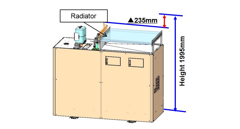
Because the system sometimes needs to be disassembled for transportation, such as when using an elevator or installing in a machine room with an access door height restriction, its design must make it easy to disassemble for transportation. Yanmar cogeneration systems are fitted with an air-cooled radiator and fan to release engine waste heat when a customer has reduced hot water demand. The radiator on the previous model was mounted in the vertical direction, with the radiator needing to be removed when the package was disassembled for transportation, meaning it was also necessary to drain the engine coolant. In contrast, the radiator in the CP35D1 is mounted in the horizontal direction, which means that the components in the top part of the package can be removed without draining the engine coolant, reducing the height for transportation by 235mm to 1,760mm (see Fig. 2). Specifically, this involved the following measures.
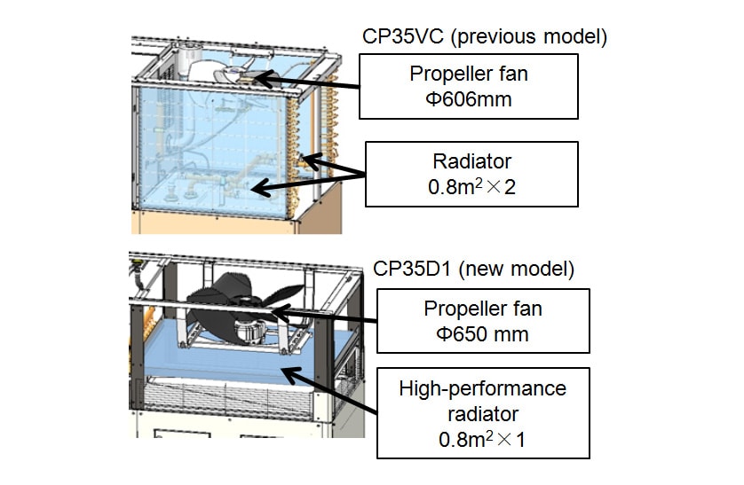
(1)Increase in fan air flow rate
Because of the limits on the depth and width dimensions, the size of the radiator needed to be reduced compared to the previous model so as to also reduce the installation space requirements. To achieve this, the air flow rate of the cooling fan was increased. The diameter of the propeller fan was increased from 606mm to 650mm to increase the air flow rate for a given fan speed.
(2)Improvement in radiator performance
As increasing the air flow rate of fan was not enough on its own to achieve the required cooling, high-performance radiator fins were also adopted. This enabled the radiator surface area in the previous 35kW model to be reduced by 50%, from two to one 0.8m2 radiators (see Fig. 3).
4.1.3.Adoption of Water Cooling
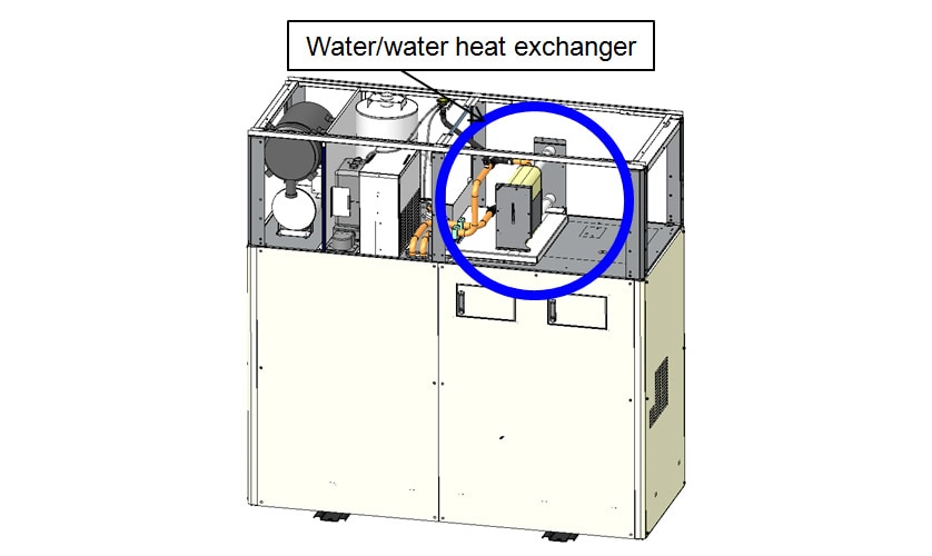
Whereas the previous model was only available with air cooling, whereby a radiator was used to release engine waste heat when demand for hot water was low, a water cooling option has been added for the CP35D1.
The radiator used on air cooled models was replaced by a water/water heat exchanger (see Fig. 4). The use of water to release waste heat was implemented with the minimum possible modifications. This eliminated the need for the large ventilation system that was previously required to release engine waste heat at indoor installations (approximately 9,800m3/h per cogeneration system). By simplifying ventilation installation work, this not only allows the system to be installed with water cooling at sites where providing ventilation is difficult, but it also makes replacement installations easier at sites that already have cooling towers or similar infrastructure to which the system can be connected.
4.2.Higher Heat Recovery Efficiency
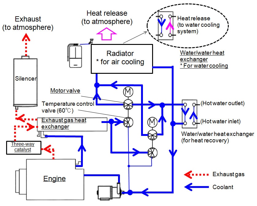
Fig. 5 shows the heat recovery flowchart for the engine. Coolant discharged from the pump takes heat from the engine and the exhaust gas heat exchanger, and then utilizes it to produce the secondary hot water via the water/water heat exchanger. To improve energy efficiency, the following measures were adopted to increase the heat recovery efficiency to 54.5% (3.5 percentage points higher than the previous model).
(1)Optimization of exhaust gas heat exchanger
The use of stoichiometric combustion in the engine resulted in a higher exhaust gas temperature. Moreover, to recover more heat from the exhaust gas, an optimal circuit design was adopted for the exhaust gas heat exchanger by revising the pipe diameter and layout to ensure that the exhaust gas path was long enough. This achieved a heat recovery efficiency 1.9 percentage points higher by successfully recovering 41% of the heat losses (heat that was unable to be recovered) on the previous model.
(2)Reduction in pressure losses in coolant circuit
To reduce pressure losses in the coolant circuit, components with low pressure losses were selected for the water/water heat exchanger, the motor valve and temperature control valve were located in parallel, and improvements were made to things like the pipe length, the number and angle of curves, and the direction of flow at branch and joint. These changes improved the flow rate by 7% using a water pump with the same specifications. The faster water flow added 0.2 percentage point to the heat recovery efficiency by increasing the amount of heat recovered from the engine and exhaust gas heat exchanger.
(3)Optimization of engine cooling
A feature of downsized engines is that the same calorific amount of combustion results in a higher overall engine temperature than it would in a larger engine. Accordingly, the internal cooling circuit used on the new engine was significantly upgraded from that on the lean combustion engine to maintain the durability against the heat. This added 1.4 percentage points to the heat recovery efficiency by increasing the amount of heat recovered from the engine.
5.Conclusions
The CP35D1 described in this article was successfully developed as a cogeneration system for helping with both energy efficiency and power saving that satisfies the more demanding requirements of customers by being easier than previous models to install at indoor sites and delivering even greater energy efficiencies for customers with a high level of demand for heat.
As the gas engine also complies with the US EPA emission regulations, it is able to be sold in the USA. Energy efficiency and contributing to the environment are challenges not only in Japan but throughout the world. Yanmar intends to continue working to help resolve worldwide energy and environmental problems.
-IMPORTANT-
The original technical report is written in Japanese.
This document was translated by Research & Development Management Division.
Author