Development Division
Large Power Products Management Division
Power Solution Business
YANMAR Technical Review
Development of 6EY26DF Dual-Fuel Engine: Compliant with IMO Tier 3
Abstract
Rising demand in recent years for lower engine emissions has led to growing interest in marine gas engines and their ability to significantly reduce emissions of nitrogen oxides, sulfur oxides, particulate matter, and carbon dioxide. Dual-fuel engines are seen as a potential solution for marine environmental problems, also offering the flexibility to run on either gas or diesel and the redundancy that comes from an ability to continue running in diesel operation mode in the event of problems in gas operation mode. This article describes the design and technical characteristics of the 6EY26DF four-stroke dual-fuel engine developed by Yanmar for marine propulsion.
1. Introduction
With increasing restrictions having been placed on emissions of atmospheric pollutants over recent years, there is a need for further reductions in the emission of nitrogen oxides (NOX), sulfur oxides (SSOX), and particulate matter (PM) in the exhaust of marine engines. Similarly, rising awareness of global warming is driving demand for reductions in carbon dioxide (CO2), a greenhouse gas (GHG).
A wide variety of methods have been proposed for reducing the amount of atmospheric pollutants in exhaust gas. Selective catalytic reduction (SCR), in which a catalyst is used to reduce NOX emissions, works very well for this purpose but is not able to reduce the emission of SOX, PM, and CO2. Likewise, scrubbers are a good way to reduce SOX and PM but do not do much for NOX, also raising problems for the downstream treatment of the seawater used. Other options currently at the research and development stage include exhaust gas recirculation (EGR) and emulsions, but these, too, are unable to reduce all of the pollutants that are harmful to the environment. In contrast, one technology that can help reduce emissions of all of these pollutants and GHGs is the use of gas engines fueled by natural gas. As a result, use of this technology for marine engines is seen as an effective option for dealing with stricter regulation of exhaust gas emissions in marine transportation. The key features of a dual-fuel engine that combines the characteristics of both gas and diesel engines are that it provides the flexibility to run on either gas or diesel, depending on operating conditions, and that this ability to use two different fuels provides built-in redundancy. This article describes the technologies used in the 6EY26DF dual-fuel engine developed by Yanmar for marine propulsion.
2. Challenges in Development of Dual-Fuel Engine
Amid rising expectations for the use of gas engines as a means of complying with increasingly strict environmental regulations in the marine market, Yanmar commenced its development of a dual-fuel engine based on its existing 6EY26 diesel engine in the latter half of 2012.
One of the challenges that arose in initial development was the installation of the pilot fuel injection valve, which serves as the ignition source in gas operation mode (herein after gas mode), in the cylinder head. Two key reasons for this were a lack of experience at that time with fuel system that use a common rail in large engines, and the limited number of suppliers with fuel injectors able to be installed in cylinder heads. A third was the need for the work to establish both the combustion performance and the strength of the cylinder head despite its being made thinner by positioning the pilot fuel injection valve near the center of the combustion chamber and maintaining the diameters of the intake and exhaust valves.
Moreover, given that having three different fuel supply systems (the main fuel supply, pilot fuel supply, and gas fuel supply) is a key feature of the engine, other major design challenges related to fire prevention considerations (where to locate the respective fuel pipes) and adaption of the gas engine for marine use (how to manufacture the double-wall piping for the gas supply in compliance with rules of classification societies).
The engine was also equipped with various control devices and a large number of sensors. These are used for operational control, including common rail, gas injection, and fuel-air ratio control; balancing control of the respective cylinder pressures; anti-knocking control; transient control used during acceleration and switching between operation modes; safety interlocks for starting and switching between operation modes; and realization of fault diagnosis on each component.
This was the first time Yanmar had attempted to combine such a diverse mix of equipment and functions on the same engine.
3. Key Features and Design of Dual-Fuel Engine
Table 1 lists the specifications of the newly developed dual-fuel engine. In gas mode, the engine uses compression ignition whereby the pilot fuel injection valve injects a small quantity of liquid fuel, with the powerful and stable ignition performance of the pilot fuel injection making the engine suitable for marine propulsion.
Table 1 Specifications of Dual-Fuel Engine
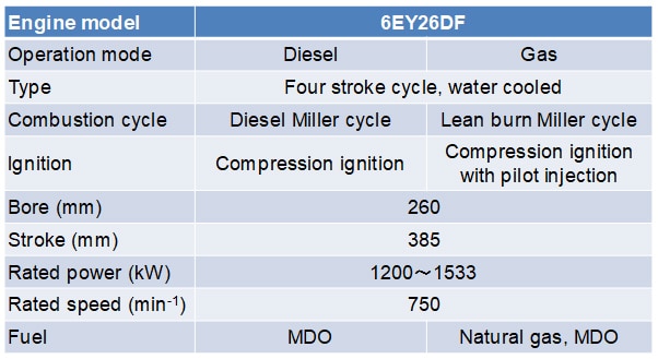
Fig. 1 shows external views of the dual-fuel engine. The pilot-common rail systems are located on the operation side along with the conventional diesel fuel injection system. The gas piping is located on the exhaust side, with double-wall piping used throughout the gas supply as a safety feature for preventing gas leaks (compliance with rules of classification societies). The charge and exhaust system uses constant-pressure turbocharging, with a waste gate valve fitted to the turbocharger's exhaust gas inlet and a compressor bypass valve to its charge air outlet for air-fuel ratio control in gas mode.
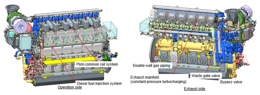
Fig. 2 shows a cross-section of the cylinder head. The main fuel injection valve, which is used in diesel operation mode (hereinafter diesel mode) and when starting or stopping, and the pilot fuel injection valve, which is the ignition source in gas mode, are located in the center of the combustion chamber. The gas admission valve to supply fuel gas is located on the air intake of the cylinder head. The pilot fuel is injected constantly, accounting for approximately 1 % of total heat input, and the engine speed is controlled with main fuel injection in diesel mode by using an electronic speed governor. In gas mode, the main fuel injection is turned off and a lean fuel mixture of charge air and the fuel gas injected from the gas admission valve, which is introduced into the combustion chamber, is compressed and ignited by injecting the pilot fuel.
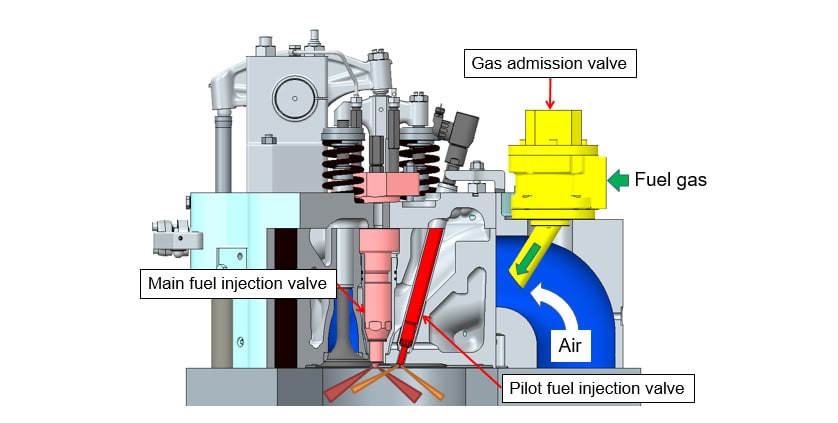
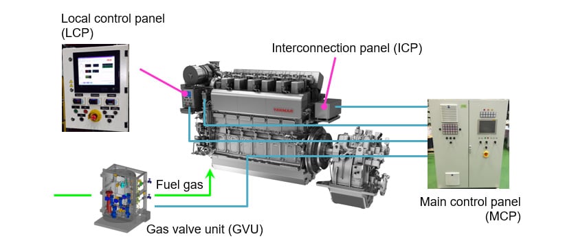
Fig. 3 shows the overall control system for the dual-fuel engine. The main control panel (MCP) attached to the hull handles the complex control functions described in the earlier section on development challenges. The MCP provides continuous monitoring information about the engine prior to starting and during operation, with touch panel controls for confirming the various engine parameters visually on screen. The local control panel (LCP), meanwhile, is equivalent to the instrument panel for a normal diesel engine, also including a touch panel for showing engine parameters and operational control levers for starting or stopping the engine and switching between operation modes.
4. Control and Performance of Dual-Fuel Engine
4.1. Air-Fuel Ratio Control
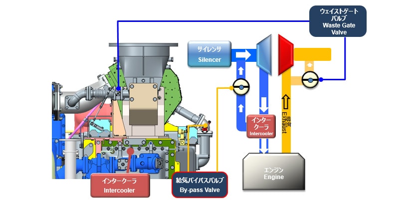
Fig. 4 shows the engine's air-fuel ratio control system. Precise control of how much fuel gas and air to supply is needed to keep the engine running smoothly during rapid acceleration or deceleration in gas mode. Electrically driven high-speed control of the fuel gas supply can be performed by the gas admission valve located on the air intake of cylinder head (see Fig. 2). For the air supply, however, the slow response of the turbocharger during rapid acceleration may result in knocking due to insufficient air. Similarly, misfiring may occur during rapid deceleration due to an oversupply of air. To cope with this slow response in the amount of air charged during transient conditions, the air charge system has been equipped with a compressor bypass valve that can control the boost pressure as required. This is done by using a bypass circuit in the air charge system that, during normal running, recirculates some of the air charged to the engine back to the turbocharger inlet. Furthermore, main engines require air-fuel ratio control that can handle wide range of engine speeds from the low (with low air flow rate) to the high (with high air flow rate). Air-fuel ratio control by using a waste gate valve is provided for this purpose.
4.2. Knocking Detection and Prevention
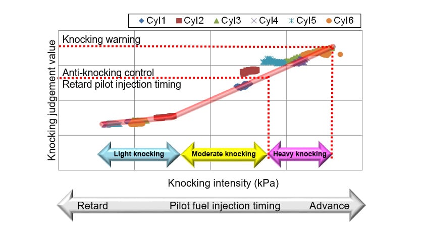
Knocking is the self-ignition of unburned fuel-air mixture in the combustion chamber at high temperature and pressure and may cause serious damage to the engine due to the sudden pressure and temperature rise. To detect this abnormal combustion, the knocking intensity is calculated by using a pressure sensor located on the combustion surface of the combustion chamber to analyze the cylinder pressure for each cycle, with the knocking judgement value being defined as integrating knocking intensity that exceeds a certain amount. Fig. 5 shows the relationship between the knocking intensity and the knocking judgement value. Knocking is prevented by automatically retarding pilot fuel injection timing based on this judgement value.
4.3. Switching between Operation Modes
Fig. 6 shows an example of switching between different operation modes in the dual-fuel engine. In this example, the engine starts in diesel mode before switching to gas mode. In case a problem occurs in gas mode, the engine is switched immediately back to diesel mode. If no such problems occur, the engine is switched from gas mode back to diesel mode prior to stopping.
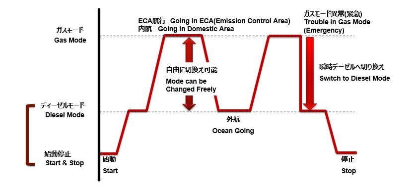
Fig. 7 shows the actuator outputs of the diesel and gas governor during switching from diesel to gas mode. Switching to gas mode is performed gradually and the reason is to prevent knocking due to fluctuations in the air-fuel ratio during the operation mode switching. While it takes about 30 seconds to switch from diesel to gas mode, by controlling the engine as shown in Fig. 7, it is possible to switch operation mode anywhere in the engine's load range.
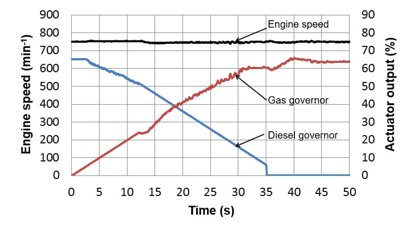
Fig. 8 shows the actuator outputs of the diesel and gas governor during switching from gas to diesel mode. As knocking does not occur in diesel mode, it is possible to perform this mode switch instantaneously, anywhere in the engine's load range. What this means is that, in the event of a fault that prevents the engine from running in gas mode, the engine can be switched immediately to diesel mode and continued to run without stopping.

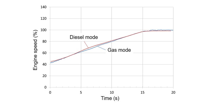
4.4. Acceleration Performance
Fig. 9 shows a comparison of the acceleration performance under loaded condition in gas and diesel mode. In both modes, the engine is able to accelerate from idling to 100 % rated load in 15 seconds.
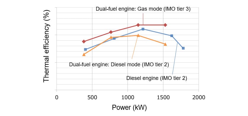
4.5. Thermal Efficiency
Fig. 10 shows the results of the thermal efficiencies of the dual-fuel engine and a conventional diesel engine that complies with IMO tier 2. In gas mode, the dual-fuel engine achieves a higher thermal efficiency than the IMO tier 2 compliant diesel engine.
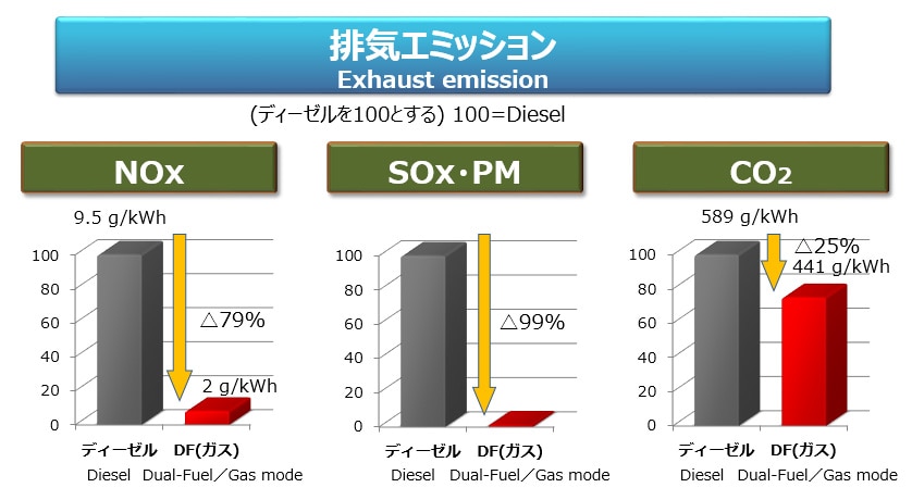
4.6. Exhaust Emissions
Fig. 11 shows a comparison of exhaust emissions of the dual-fuel engine (in gas mode) and the IMO tier 2 compliant diesel engine. Compared to the diesel engine, emissions in gas mode are 79 % lower for NOX, 99 % lower for SOX and PM, and 25 % lower for CO2. The reduction in NOX means that the engine satisfies the IMO tier 3 regulation when in gas mode.
5. Conclusions
This article has described the technological challenges and techniques used in the dual-fuel engine that complies with the IMO tier 3 regulations. This engine, the 6EY26DF, went on sale in April 2016, with the first two units, sold to Mitsui O.S.K. Lines as the main engines for an LNG tug boat, being delivered in September 2018, and with two further engines to be supplied in January 2019 for installation as the main engines of a bunkering tanker operating in Singapore. In the future, Yanmar intends to continue work on expanding the product range and further improving the reliability of dual-fuel engines with excellent environmental performance in terms of compliance with exhaust gas regulations.
Reference
- ◊This article is a revised version of one that appeared in the journal of the Japan Institute of Marine Engineering (Vol. 51, No. 2).
-IMPORTANT-
The original technical report is written in Japanese.
This document was translated by Research & Development Management Division.