Development Division
Technology & Production Division
YANMAR POWER TECHNOLGY CO., LTD.
YANMAR Technical Review
Whirl Vibration Analysis of Engine Cooling Fan System
Technology for Adapting to Various Engine Installation Designs
Abstract
This paper describes a whirl vibration analysis method for cooling fan systems for application to various engine installation designs. The coupled vibration of the blade system and shaft system was formulated using a four-degree-of-freedom model, and a method was developed to quickly evaluate critical speed. Additionally, dynamic behavior is simulated using Multi body dynamics, enabling detailed design optimization of support structures. Experimental validation confirms the accuracy of the proposed method, its effectiveness.
1. Introduction
Yanmar’s industrial engines are custom designed to meet the quality standards, engine room layouts, and other requirements of a wide variety of different industrial machinery. To eliminate rework in product development for engines or vehicle bodies, it is important that design directions be assessed in the early stages of design. Cooling fan systems also fall within the scope of this customization, with the type of cooling fan, its location, and its speed relative to the crankshaft speed being among the factors to be considered. Recent years have also seen a trend toward heavier cooling fans, including increased use of reversible fans and cooling fans equipped with a clutch(1). As heavier cooling fan systems tend to have a lower resonant frequency, this trend has implications for durability due to the heightened risk of resonance with engine vibration. This makes it essential to design the support stiffness and overhang of each cooling fan used in an engine appropriately.
This article describes an evaluation technique that is intended to make the customization of design more efficient and that works by dividing the purpose of analysis into two steps based on the design stage. That is, the evaluation technique is a two-step process with separate initial and detailed evaluations. The initial evaluation uses a model with four degrees of freedom to analyze coupled vibration of the blade and shaft systems to quickly identify which speed poses a risk. If such a critical speed is identified by the initial evaluation, a dynamic analysis is performed to predict the dynamic behavior of the cooling fan and review the detailed geometry of the support. By doing so, a design that satisfies the requirements can be achieved efficiently while also shortening the design time and reducing the cost of prototyping and testing.
2. Evaluation Technique
2.1. Evaluation Using Model with Four Degrees of Freedom
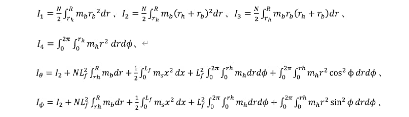
The cooling fan system is represented by the model shown in Figure 1 that has four degrees of freedom. This model is used to determine the coupled vibration of the blade and shaft systems(2). The kinetic energy  of the system can be expressed by the following equation.

Here,  and
and  are the shaft angles,
  and
and  are blade angles in the reference coordinate system, and
  is the angular velocity of the fan.
The moments of inertia,  ,
,  ,
,  , and
, and  are given by the following equations.
Here,
 : Number of blades
 ,
,  ,
,  : Masses of shaft, hub, and a single blade
 ,
,  : Blade radius and hub radius
 : Distance from the hub to a point on the blade
 : Distance from the center of the hub to a point on the hub
 : Overhang
The potential energy  is:
is:

Here,  ,
,  , and
, and  are the support stiffness for the shaft and blade.
The Lagrangian  is:
is:

Solving the Lagrange equations of motion gives:

These Lagrange equations can be expanded to solve the following equations of motion.

From these equations of motion, it is possible to solve the quartic equation for the natural angular frequency of vibration  .
.

This equation can be solved analytically to obtain the natural angular frequency of vibration in the stationary coordinate system. Due to the gyroscopic effect, the natural angular frequency of vibration has both forward and backward natural angular frequencies, and the frequency changes depending on the cooling fan speed. Moreover, the blade system and shaft system each have their own forward and backward natural angular frequencies, giving a total of four.

2.2. Multi-body Dynamics Model and Experimental Apparatus
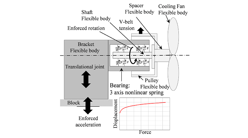
Figure 2 shows a summary diagram of the multi-body dynamics model. The rotating part and bracket are treated as elastic bodies. The multi-body dynamics model defines the bearing between the rotating parts and bracket as a non-linear spring and dashpot. The characteristics of the bearing’s non-linear spring depend on its specifications, including the load on the bearing, roller width, ball diameter, and number of moving parts(3). The bracket is connected to a rigid block, which in practice will likely be the cylinder block. This rigid block is only capable of translational motion in the vertical direction and experiences an enforced acceleration that corresponds to the vertical vibration from the four-cylinder engine while also imparting an enforced rotation to the rotating part. Note that the multi-body dynamics model considers the gyroscopic effect in the rotating part.
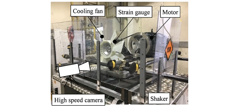
Figure 3 shows a diagram of the experimental apparatus used to assess the accuracy of the analysis model. The cooling fan system was mounted on an electromagnetic shaker that generated vertical vibrations to replicate the up and down vibration from a four-cylinder engine. While this was happening, the cooling fan was driven via a V belt and motor. A strain gauge was attached to the bracket and used to identify the point where resonance occurred. The cooling fan was run at constant speed, and a sweep of vibrational frequencies was applied using constant acceleration. Where resonance occurred during this frequency sweep was determined from the output of the strain gauge, thereby obtaining the natural frequency for whirling vibration. A high-speed camera was also used to capture shaft centerline displacement during resonance, as seen from the front of the cooling fan.
3. Results of Assessing Evaluation Technique
3.1. Results of Critical Speed Prediction
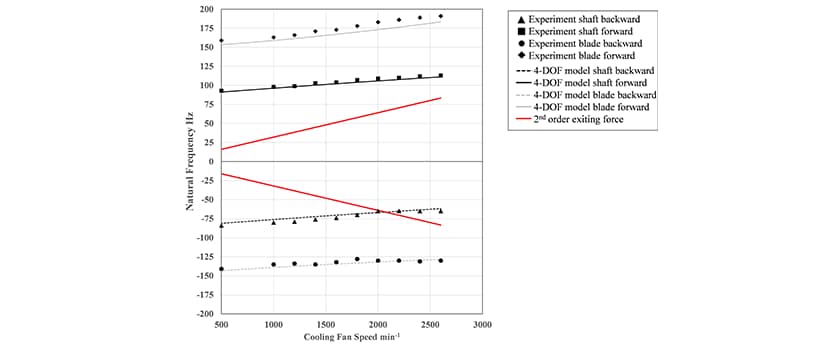
Figure 4 shows a comparison of the natural frequencies of vibration calculated by the model with four degrees of freedom and obtained from the shaking test. The curves in Figure 4 show the natural frequencies calculated by substituting the rigidity of the mounting and the mass values for the blades and shaft into the equations given above. A positive natural frequency indicates forward whirl, and a negative value indicates backward whirl. Four resonance points were identified in the experimental testing. These correspond to the vibration modes of the blade and shaft systems for forward and backward whirl, respectively. The natural frequencies calculated by the model with four degrees of freedom showed the same tendencies as the test results and had a prediction error of less than 6%. The red lines in the figure represent the frequency components (second-order rotation) for the exciting force (vertical vibration from the four-cylinder engine) when the crank shaft and cooling fan are both rotating at the same speed. The critical speed (the resonant point) occurs where the frequency of the exciting force intersects the natural frequency. If such a resonant point is identified in the initial evaluation, action is taken to consider how the critical speed can be avoided, such as by changing bearing specifications, overhang length and support stiffness. If this resonance cannot be avoided within the design constraints, the process moves on to performing a detailed evaluation using mechanism analysis.
3.2. Prediction Results of Multi-body Dynamics and Geometry Improvement
Figure 5 shows a comparison of the centerline displacements measured using the high-speed camera and calculated by the mechanism analysis. The centerline displacements at 70 Hz in experimental testing and 67 Hz in the analysis results are in the direction opposite to the direction of cooling fan rotation (backward whirl), whereas the resonance at 107 Hz in experimental testing and 102 Hz in the analysis results are in the same direction as the cooling fan rotation (forward whirl). There was good agreement between the behavior of the centerline in experimental testing and in the analysis results, being elliptical in both cases.
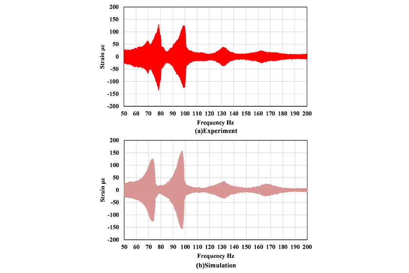
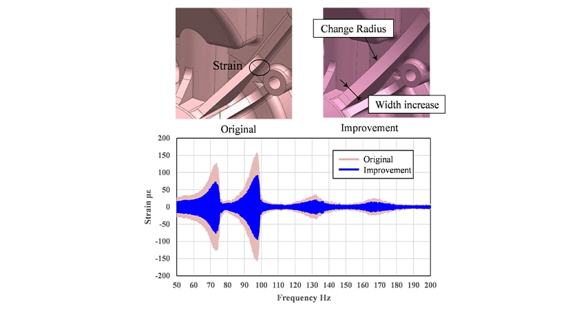
Figure 6 compares the output of the strain gauge on the bracket with the predictions made by the multi-body dynamics. The experimental testing and prediction results are in good agreement, both showing an increase in the amplitude of vibration in the vicinity of 75 Hz and 98 Hz. Figure 7 shows the predicted strain in the bracket after changes to its shape. The rib radius was increased from 5 mm to 8 mm to reduce strain in the rib and its width was increased by 2 mm. While these changes to the geometry did not change the speed at which resonance occurred, they reduced the strain by 46 % at 75 Hz and 43 % at 97 Hz. This indicates that the redesign did not change the natural frequency but did reduce strain through localized changes to the rigidity of the affected locations. These results demonstrate that multi-body dynamics model can be used to review the detailed geometry of system components.
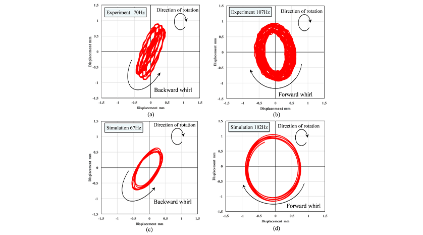
(a) Experiment: Backward Whirl, (b) Experiment: Forward Whirl,
(c) Analysis: Backward Whirl, (d) Analysis: Forward Whirl
4. Conclusions
Yanmar has developed a desktop evaluation technique for assessing how well engine cooling fan systems can withstand vibration and has performed a comparison of measurement and analysis results to assess its suitability. Custom design for use in a wide variety of machinery calls for other such techniques that can reconcile engine development and body development, not just the technique described here. In the future, Yanmar will continue working to improve its technologies to ensure that it can supply the best possible engines.
This article is a partially revised reprint of an article that appeared on pages 489-496 in Vol. 82, No. 5 of the Journal of the Japanese Society of Agricultural Machinery and Food Engineers and is published here with the permission of the society.
5. References
- (1)Bennett, S.: Medium/Heavy Duty Truck Engines, Fuel & Computerized Management Systems 4th Edition. Delmar Pub, New York, p.207-208, 2012
- (2)Cecrdle, J.: Whirl Flutter of Turboprop Aircraft Structures, Woodhead Publishing, Cambridge, p.125-132, 2015
- (3)Osami Matsushita, Masato Tanaka, Masao Kobayashi, Shinsuke Koike, Hiroshi Kanki: Vibrations of Rotating Machines, Corona Publishing, Tokyo, p.82-86, 2012
-IMPORTANT-
The original technical report is written in Japanese.
This document was translated by Innovation & Technology Division, Technology Strategy Division.
Author