Development Division
Yanmar Blue Tech Co., Ltd.
YANMAR Technical Review
Hull Cleaning System
Development of New Products to Solve Marine Environmental Problems
Abstract
The hull fouling of ocean-going ships is a global problem, both a biosecurity threat due to the unwanted transfer of organisms between ecosystems and a cause of higher GHG emissions due to increased drag.
These issues are generally addressed by dry docking every one to three years to wash off any biological fouling from the hull.
Recently, however, a growing number of countries have been mandating the hull cleaning of ships before they can enter port and this is driving demand for easy and frequent cleaning methods.
In response, Yanmar has developed an underwater hull cleaning ROV for large vessels that includes a mechanism for collecting the biofouling residue generated during cleaning.
The system can quickly wash adhering organisms off the hull while also filtering and collecting the removed material to prevent it from polluting the surrounding marine environment.
Yanmar believes that its technology for the underwater removal of biofouling will help to prevent environmental damage due to the unwanted transfer of organisms between marine ecosystems while also reducing GHG emissions.
1. Introduction
The hull fouling of ocean-going ships is a global problem, both a biosecurity threat due to the unwanted transfer of organisms between ecosystems and a cause of higher GHG*1 emissions due to the resulting increase in drag. This has led nations around the world to introduce laws mandating hull cleaning. The problem has typically been addressed by bringing vessels into a dry dock to clean their hulls every one to three years and also by having divers perform underwater cleaning to remove the buildup of adhering organisms.
Frequent removal is needed as marine organisms will start growing again on a hull within a few weeks of it being cleaned. Unfortunately, underwater cleaning by divers is onerous work that exposes them to hazards. This has created a need for some way of performing this cleaning frequently and more safely.
Recognizing the public interest in this issue, Yanmar has been working on the development of hull cleaning ROVs*2 that can operate underwater and techniques for recovering the debris*3 created by the cleaning work. The outcome of this work was the development of a hull cleaning system. This involved addressing the following technical challenges.
① How to equip the ROV for rapid ship cleaning
② How to recover the debris without it dispersing into the water
This article presents an overview of this hull cleaning system and the work done to address these technical challenges.
- ※1GHG: Greenhouse gas
- ※2ROV: Remotely operated vehicle
- ※3Debris: The residue of marine organisms removed from a ship’s hull
2. Hull Cleaning System Profile
2.1. How Hull Cleaning is Performed
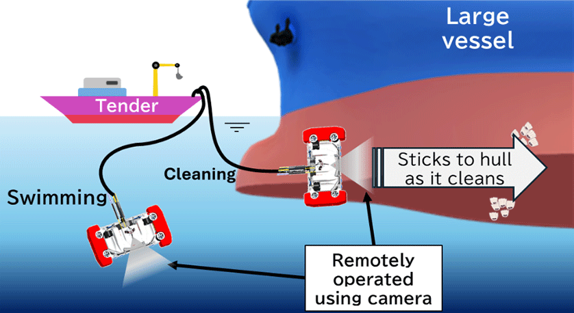
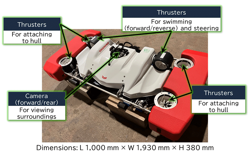
Yanmar’s hull cleaning ROV, the HC12, is operated remotely from a tender or other support vessel and performs cleaning by attaching itself to a ship’s hull, as shown in Figure 1. The ROV has six thrusters for propulsion (Figure 2 ) and can operate in two different modes whereby it either swims freely or moves over the contours of the hull. Efficient hull cleaning is achieved by means of high-pressure water jets that operate as the ROV travels across the hull. The operator uses a wireless controller to pilot the ROV remotely from the tender while viewing the feed from the onboard camera and sensors.
2.2. Overview of Hull Cleaning System
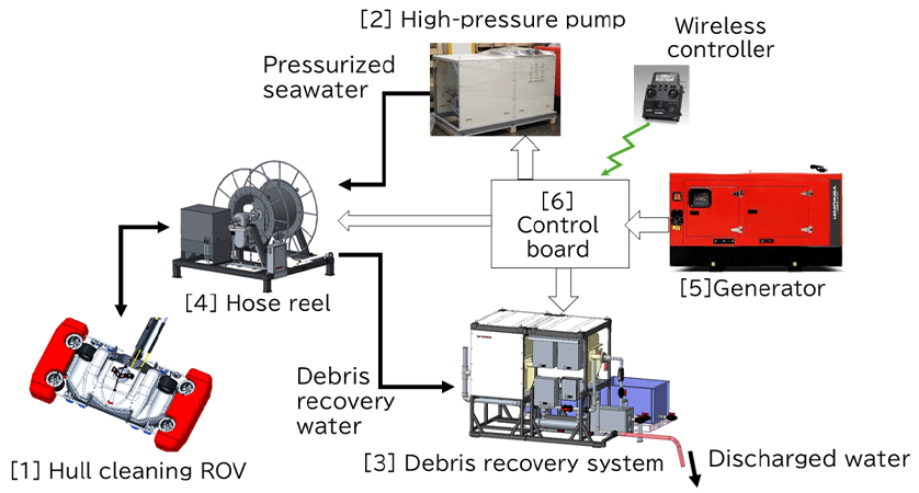
Figure 3 shows a block diagram of Yanmar’s hull cleaning system. As noted above, the system is made up of an ROV [1], high-pressure pump [2], debris recovery system [3], hose reel [4], electrical generator [5], and control board [6]. All of these system components other than the ROV itself are installed and operated on the deck of the tender.
The high-pressure pump [2] supplies pressurized seawater to the cleaning unit on the ROV [1]. To prevent biofouling debris dislodged from the hull from dispersing into the surrounding water during underwater cleaning, the debris recovery system [3] pumps the contaminated water up to the tender where it is passed through a filter to recover this material. The filtered water is sterilized and then discharged back into the surrounding waters. The hoses through which the pressurized and contaminated water is transferred are reeled in and out using the hose reel [4]. They are 100 m in length to allow for the cleaning of large vessels. The electrical generator [5], and control board [6] supply power to the other equipment ([1] to [4]) and control the ROV [1].
3. Efforts to Overcome Technical Challenges
3.1. Equipping ROV for Rapid Ship Cleaning (Increasing ROV Speed)
A cleaning system operator needs to be able to clean a large vessel in a single day, a surface area that may exceed 14,000 m2. Unfortunately, past ROVs have only been capable of cleaning around 1,200 to 1,500 m2 per hour. At this work rate, cleaning 14,000 m2 would take 10 to 12 hours. As this makes it difficult to complete cleaning in a single day, the work rates of past ROVs have been considered inadequate for the task. Accordingly, Yanmar set a maximum work rate of 2,000 m2 per hour as its development target, a speed that would enable a cleaning time of 7 hours and allow vessels to be cleaned in a single day.
To enable this faster work rate, it was necessary to design the ROV body to be as small as possible and to keep drag to a minimum.
To achieve this smaller size, the amount of onboard equipment on the ROV was drastically reduced by relocating components such as the motor controller and debris recovery pump to the tender. This succeeded in shrinking the ROV volume from 1.5 m3 to 0.7 m3.
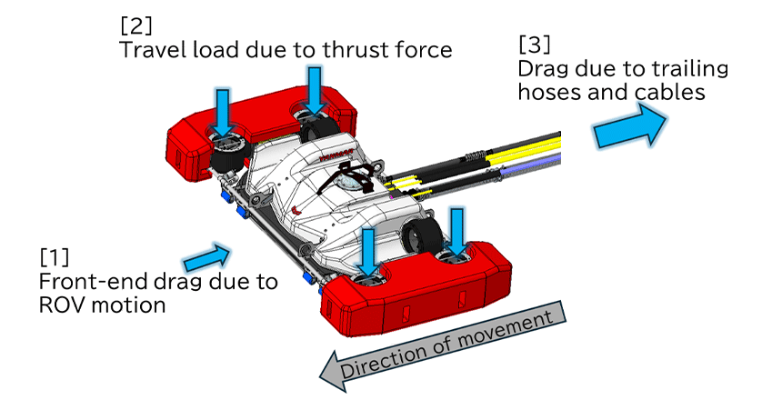
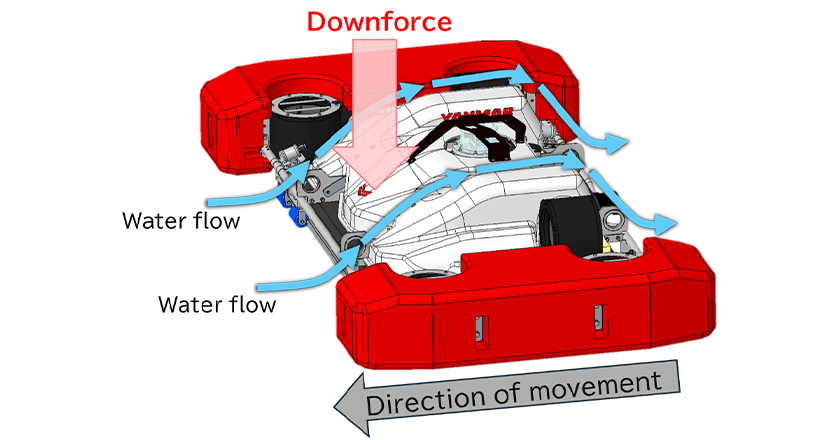
The next step was to look at what could be done with the body design to minimize drag. The ROV achieves its speed by having sufficient propulsive force to overcome the total drag it experiences when performing cleaning at the target speed. As shown in Figure 4, drag is made up of three parts: [1] The resistance due to the front of the ROV as it moves through the water, [2] The load due to the thrust force that occurs as the ROV moves over the vessel’s hull, and [3] The resistance due to the trailing hoses and cables. Of these, reducing front-end drag [1] was identified as a key issue because of the strong influence it has on the mobility of the underwater vehicle. Accordingly, Yanmar designed the ROV with a thin and streamlined shape, as shown in Figure 5. The body was also given a contoured design such that the drag associated with forward movement through the water would generate downforce and help the ROV stay reliably attached to the hull.
These efforts to shrink the body size and minimize drag succeeded in reducing total resistance when cleaning at the target speed from 660 N on the previous model to 360 N (approximate values). By equipping the ROV with thrusters sized accordingly, the target work rate of 2,000 m2 per hour was achieved.
3.2. Recovery of Debris Without Dispersal into Water (Preventing Ecosystem Disruption by Spread of Introduced Species)
If the debris generated by hull cleaning spreads into the surrounding waters, it poses a risk of disruption to the ecosystem due to introduced species. Instead, a mechanism is needed that can suction the debris up into the tender and filter it to recover this material.
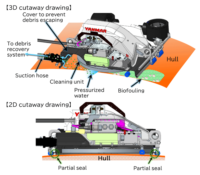
As the Yanmar ROV washes off adhering marine life by spraying pressurized water onto the hull from underwater, it needs a way to prevent the resulting debris from escaping. To this end, the cleaning unit is fitted with a debris cover that forms a partial seal (when attached to the hull) and is connected at the rear to a hose through which the debris is suctioned back to the recovery system. The system was designed such that the rate at which debris is suctioned back to the recovery system is faster than the supply of pressurized cleaning water, thereby generating a negative pressure that minimizes any debris escaping from the ROV during cleaning.
4. Testing of Ship Cleaning Performance
This section presents the results of testing the ROV’s work rate and cleaning performance. This involved using a prototype ROV to clean an actual ship to verify that the system achieved its design level of performance. (Note that the work rate and cleaning performance quoted here do not constitute a guarantee of actual product performance as these can vary widely depending on factors such as environmental conditions, the size and species of adhering organisms, and the hull geometry.)
4.1. Work Rate Verification
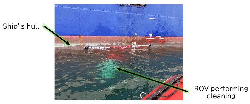
As the ROV has a cleaning width of 1.2 m, achieving the target work rate of 2,000 m2/hour requires that it operate at a speed of 28 m/minute. Measurement of the actual speed (which was estimated from video footage) was done by attaching the ROV to the ship’s hull and operating it at its maximum cleaning output (Figure 7). The average speed measured during this testing was 39.2 m/minute, more than enough to satisfy the target work rate of 2,000 m2/hour.
4.2. Verification of Cleaning Performance
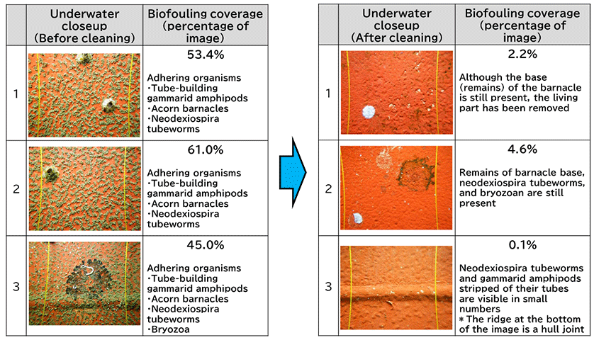
Figure 8 shows the extent of biofouling on the ship’s hull before and after the above cleaning test was conducted. To verify the biofouling removal performance, the removal ratio was determined from an analysis of the close-up images shown in Figure 8. This found that the system had achieved a high level of hull cleaning, with an estimated 95.7% removal ratio. That is, the coverage area of adhering organisms, which had ranged between 45.0 and 61.0% (mean: 53.1%) prior to cleaning, had been reduced to 0.1 to 4.6% (mean: 2.3%) afterwards.
Figure 9 shows debris suctioned up from the ROV during the test and water discharged from the debris recovery system after filtering. While it was impossible to determine the actual percentage of biofouling that was recovered given that the cleaning was performed at sea, it was verified that organisms dislodged from the hull were suctioned up and properly filtered.
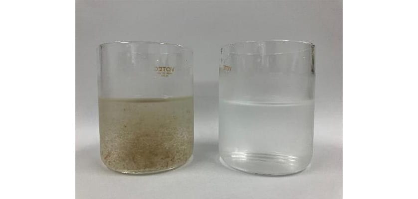
and Water After Filtering (Right)
5. Conclusions
This article has described a hull cleaning system developed by Yanmar and how the technical challenges associated with hull cleaning (listed in section 1) were addressed. The work was able to overcome these challenges and successfully developed a hull cleaning ROV with world-leading cleaning speed. By providing a means of cleaning ships safely and frequently, Yanmar believes that this work is contributing to the creation of sustainable societies by preventing environmental damage due to the unwanted transfer of organisms between marine ecosystems and by reducing GHG emissions.
Unfortunately, the current ROV is not equipped with the ability to determine its own overall location in real time while operating underwater, forcing operators to be tentative in their steering of the ROV as they rely on the feed from the underwater camera to determine its location. Depending on the condition of the water where the cleaning is being performed, their work may also be impeded by having to operate in dirty water. Accordingly, future plans include the development of techniques for underwater self-positioning and for improving the underwater camera’s image quality with the goal of further improving maneuverability and cleaning performance. To this end, Yanmar has established a joint venture called Yanmar Blue Tech Co., Ltd., partnering with Sony Group Corporation, a company that possesses technology for underwater sensing. Underwater self-positioning, in particular, is recognized as a promising field where technology remains lacking internationally, but where there is scope for future application on a wide variety of vehicles used for underwater operations. In its business that deals with these underwater vehicles, Yanmar intends to continue its efforts to resolve customer challenges.
- *Development of the technologies described in this article was supported by the Nippon Foundation (a public interest incorporated foundation) through a new product development assistance program of the Japan Ship Machinery and Equipment Association.
-IMPORTANT-
The original technical report is written in Japanese.
This document was translated by Innovation & Technology Division, Technology Strategy Division.
Author