Fundamental Technology Research Center
Research & Development Center
Innovation & Technology Division
YANMAR HOLDINGS CO., LTD.
YANMAR Technical Review
Investigation of Fundamental Combustion Characteristics of Hydrogen Dual-Fuel Engine
Combustion Modeling Using Single-Cylinder Engine Testing and Simulation
Abstract
In pursuit of a carbon-neutral society, the movement toward decarbonization in the international community is accelerating. Hydrogen, being flammable and non-toxic, is expected to serve as a viable alternative to fossil fuels, particularly in coastal vessels and workboats with relatively short ranges. However, several technical challenges must be addressed regarding its use in engines, including the suppression of abnormal combustion and the reduction of NOX emissions. To tackle these issues, we investigated a hydrogen dual fuel engine in which hydrogen is pre-mixed and ignition is controlled by diesel spray. Our findings indicate that increasing the hydrogen energy ratio under high boost conditions can lead to stable combustion and maximize CO2 reduction effects. This paper presents the combustion development of medium to large-sized hydrogen engines, supported by experiments and numerical simulations conducted with a single-cylinder hydrogen dual fuel engine.
1. Introduction
In pursuit of a carbon-neutral society, the movement toward decarbonization in the international community is accelerating. In the case of medium- and large-sized marine engines, this transition calls for the adoption of carbon-neutral fuels and a shift away from fossil fuels. Fuel flexibility is also in demand in the marine engine market, with a particular focus on dual-fuel (DF) engines able run on both carbon-neutral and fossil fuel.
One such carbon-neutral fuel is hydrogen. Being flammable and non-toxic, it is expected to serve as a viable alternative to fossil fuels, particularly in coastal vessels and workboats with relatively short ranges. However, several technical challenges must be addressed regarding its use in engines, including the suppression of abnormal combustion and the reduction of NOX emissions, issues that hydrogen DF engines likewise need to overcome.
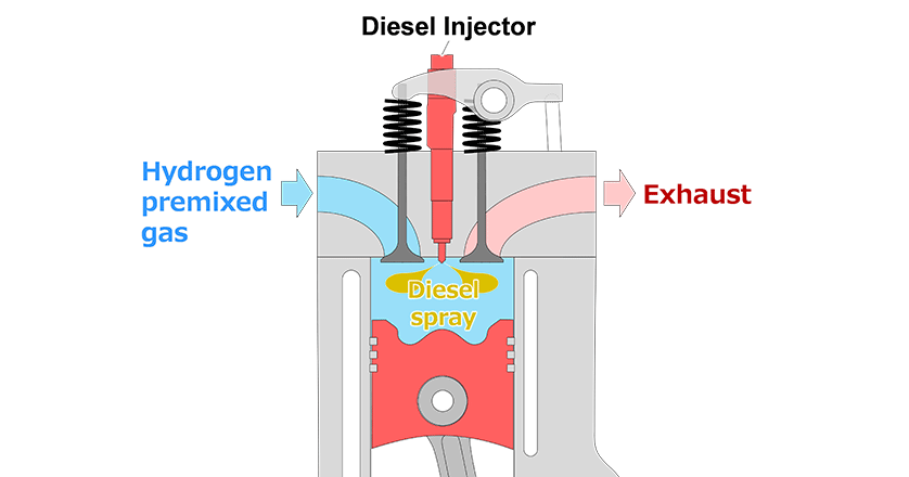
As there has been little research and development on hydrogen DF engines to date, it is essential that this work be underpinned by first gaining an understanding of the engines’ fundamental combustion characteristics. This article describes combustion testing using a single-cylinder hydrogen DF engine (see Figure 1), the development of a combustion model, and the application of this model to multi-cylinder engine development.
2. Combustion Testing Using Hydrogen DF Engine
2.1. Test Engine and Testing Conditions
Figure 2 shows the test engine and lists its specifications. The single-cylinder four-stroke hydrogen DF engine has a displacement of 1142 cm3. The cylinder has a toroidal combustion chamber with a compression ratio of 14.3. It is equipped with a common-rail diesel injection mechanism that includes a supply pump with external motor drive for fuel compression.
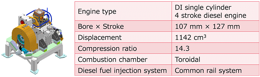
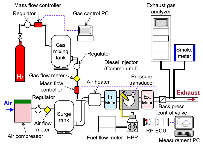
Figure 3 shows a diagram of the test apparatus. The intake air is compressed by an electrically driven compressor. The intake system includes a surge tank to dampen pressure fluctuations and uses a pressure-reducing valve to reduce the intake manifold pressure to the desired value. The primary regulator at the outlet of the pressurized hydrogen cylinder reduces the pressure to approximately 0.7 MPa and supplies it to the intake system via a flow control valve (mass flow controller). The hydrogen is mixed with fresh air on the inlet side of the air heater that adjusts the temperature of the air-hydrogen mixture.
The testing was conducted at a fixed engine speed of 1200 min-1 and with a load defined in terms of the indicated mean effective pressure ( ). That is, the supply of hydrogen or diesel was adjusted to achieve the setting of 1.3 MPa. The gas fuel energy ratio (
 ) expresses the amount of energy supplied to the engine by the hydrogen fuel as a proportion of the total energy (Equation 1). Here,
  is the energy supplied by diesel and
  is the energy supplied by hydrogen.

The excess air ratio when running on diesel only (=0%) ( ) is calculated by dividing the mass flow of intake air (
 ) by the stoichiometric air-fuel ratio (
 ) and mass flow of fuel (
 ) (Equation 2).

An excess air ratio of =2.0 was set as the standard value and =2.4 as the high excess air ratio case, with being varied while the intake air pressure and were held constant. Using these conditions, the influence of the hydrogen energy ratio on the engine’s combustion and exhaust characteristics was then assessed for each of these excess air ratios.
2.2. Test Results
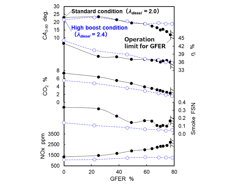
Figure 4 shows how the excess air ratio affects how the hydrogen energy ratio () influences the combustion and exhaust characteristics. For values of up to about 60%, changes in the excess air ratio had little effect on the combustion duration ( ). When the goes above about 60%, however, gets shorter when using the standard excess air ratio, with a detrimental effect on engine operation due to abnormal combustion. For the high excess air ratio case, on the other hand, the engine continued to run reliably with no major changes in combustion for values above the 60% range.
For both excess air ratios, the indicated thermal efficiency ( ) fell as the increased. A major factor in this is believed to be hydrogen premixture bypassing combustion during the valve overlap period (passing from the intake port across the cylinder to the exhaust port). Accordingly, improving will require measures to prevent this bypassing of combustion, such as modifying the intake process to use intermittent hydrogen injection to the air intake port or the use of direct cylinder injection.
Increasing also results in a reduction in the concentration of diesel-derived compounds, namely carbon monoxide (CO), carbon dioxide (CO2), and smoke. For the standard excess air ratio, the concentration of nitrous oxides (NOX) increases with increasing . In contrast, no significant increase in NOX occurs in the high excess air ratio case, even at of around 80%.
These results indicate that it is possible to combine reliable combustion with lower emissions of both CO2 and NOX by running the hydrogen DF engine with a higher excess air ratio and hydrogen energy ratio.
and Emission Characteristics
3. Modeling of Hydrogen DF Engine Combustion
3.1. Development of Combustion Model
Combustion in a hydrogen DF engine was modeled using the dual-fuel combustion model proposed by Perini et al.(1).
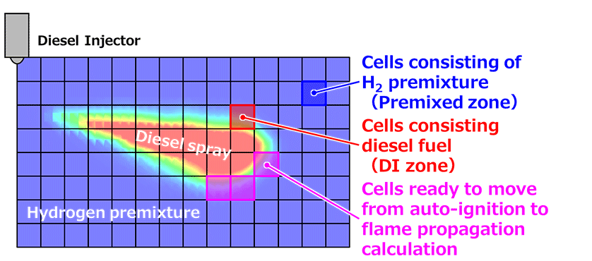
This dual-fuel combustion model uses a detailed chemical reaction model for the auto-ignition of direct-injection diesel and the G equation of flame propagation for the hydrogen premixture. Use of a detailed chemical reaction model to solve for hydrogen flame propagation would require a small mesh size and impose an impractical computational load. Instead, in this model, it is determined whether the cells in the vicinity of direct-injection diesel fuel are in a suitable state to transition from auto-ignition combustion to flame propagation. Once the volume of the identified cells is deemed sufficiently large, a transition is made from auto-ignition combustion calculations to flame propagation calculations using the G-equation model. The G equation is a scalar field equation in which the scalar value G represents the unburned gas, flame front, and burned gas. How this G value varies with flow and combustion is determined by solving a transport equation to calculate how the flame spreads through the complex flow field.
Figure 5 shows how the dual-fuel combustion model determines the type of combustion. The cells are split into direct injection (DI) zone cells that contain injected diesel fuel and premixed zone cells made up of hydrogen premixture. The determination of whether the state is suitable for transitioning from auto-ignition combustion calculations to flame propagation calculations is made when the call’s  exceeds the threshold
  (Equation 3). Here,
  is the laminar flow combustion rate (the rate of flame propagation based on local composition, temperature and pressure) and
  is the auto-ignition rate (chemical reaction rate). When the ratio of the total volume (
 ) of the cells determined to be in a suitable state for transitioning from auto-ignition combustion calculations to flame propagation calculations to the cylinder volume (
 ) exceeds the threshold (
 ), the auto-ignition combustion calculations are transitioned to flame propagation combustion calculations (Equation (4)).

The calculation and analysis of combustion in the hydrogen DF engine was done by using the dual-fuel combustion model above to simulate the auto-ignition of diesel and the flame propagation of hydrogen premixture.
3.2. Results of Combustion Model Calculations and Comparison with Test Results
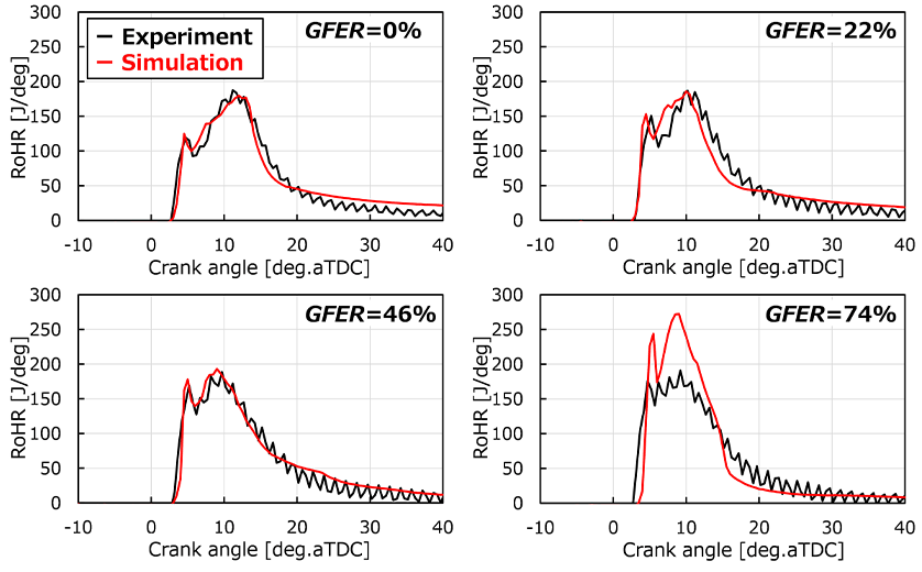
Figure 6 shows the heat release rates obtained from three-dimensional (3D) combustion simulation and a comparison with results from experimental testing. The simulation results show good agreement with experiment across all the hydrogen energy ratio(2). However, a small divergence from the test results is visible at the high value of 74% where the ignition delay is longer. It is possible that this divergence is influenced by the analysis accuracy of the temperature field in the engine cylinder or the spray conditions when the diesel injection quantity is small.
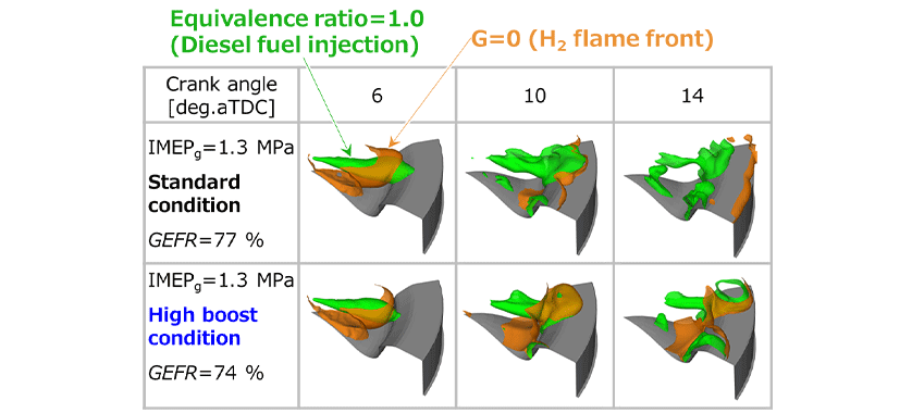
Figure 7 shows 3D representations of combustion in the hydrogen DF engine when the excess air ratio is varied for the same hydrogen energy ratio. The figures show the hydrogen flame front (brown) and an isosurface (green) of constant combined excess air ratio for diesel and hydrogen ( For all cases, once the diesel spray has self-ignited, it is the burning of the spray that is the ignition source, and it is from this point that flame propagation to the hydrogen premixture starts. As the penetration force of the diesel spray is enough for it to reach the edges of the combustion chamber, the propagation of the flame in the hydrogen premixture also reaches the edges of the combustion chamber as combustion proceeds. No major differences were evident in the diesel spray combustion, regardless of conditions (6 deg.aTDC). However, flame propagation in the hydrogen premixture becomes slower under leaner conditions (10 to 14 deg.aTDC). It is believed that this is due to the lower combustion temperature of the hydrogen premixture under lean conditions, which results in a slower flame propagation rate.
These results demonstrate that the combustion model developed here can be used for the analysis of combustion in hydrogen DF engines. The model can also be used to determine appropriate operating parameters and combustion specifications.
4. Future Applications
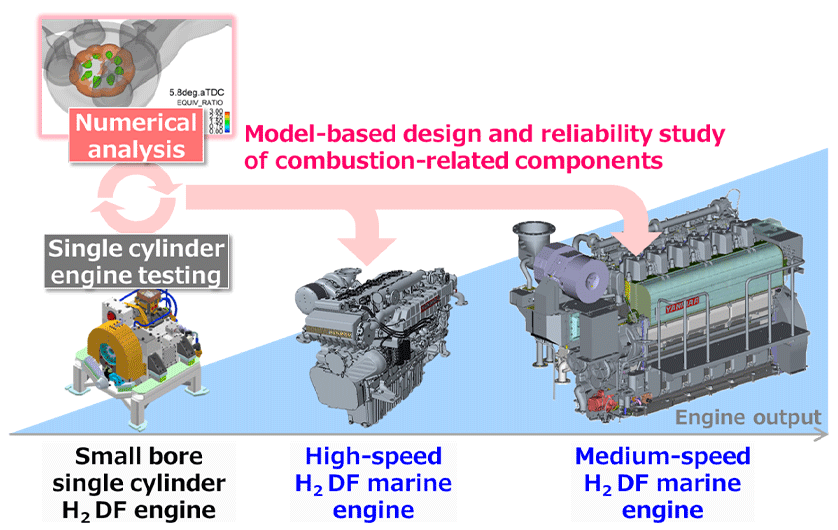
The development of a combustion model for a hydrogen DF engine has provided a three-dimensional understanding of the simultaneous progress of self-ignited combustion of diesel spray and flame-propagated combustion of hydrogen premixture. Use of the model makes it possible to study factors such as spray characteristics and combustion chamber geometry for engines with different bores and strokes. As shown in Figure 8, the model is already being applied to multi-cylinder engines in a model-based development program that uses a suitable mix of combustion simulation and engine testing.
Engines are practical energy conversion devices that can contribute to decarbonization by running on carbon-neutral fuels. In the future Yanmar intends to continue adopting new research and development practices and developing the latest engine technologies.
References
- (1)F. Perini et al.: A Dual-Fuel Model of Flame Initiation and Propagation for Modelling Heavy-Duty Engines with the G-Equation, SAE Technical Paper, 2023, 2023-32-0009, doi:10.4271/2023-32-0009
- (2)Takafumi Kamino, et al.: Combustion Process Analysis of Hydrogen/Diesel Dual-Fuel Engine by Numerical Simulation; Transactions of Society of Automotive Engineers of Japan, Vol. 55, No. 6, p. 1059-1064, (2024) in Japanese.
-IMPORTANT-
The original technical report is written in Japanese.
This document was translated by Innovation & Technology Division, Technology Strategy Division.
Author